Macurco GD-xx Operation Manual
REV – 2.0.0 [34-2900-0027-6 ] 25 | Page
5 Troubleshooting
5.1 On-Board Diagnostics
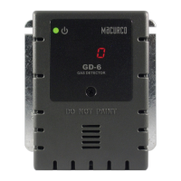
The GD-6 monitors all critical functions of the unit through software diagnostics that continuously test and verify
unit operations. If a problem is found, the unit will switch to a fail-safe/error mode or trouble condition. In this error
mode, the Alarm relay will be activated, the 4-20 mA current loop will go to 24 mA, the unit will display the error
code, the green status indicator LED light will flash, and the buzzer will chirp intermittently. The Fan relay will also
engage if the Trouble Fan Setting Option is set to “ON”. This is a safety precaution. To clear this mode, simply turn
off power to the unit for a few seconds or push the TEST switch (inside the unit). This will cause the unit to restart
the 1-minute self-test cycle.
5.1.1 4-20mA troubleshooting
• 0 mA is most likely a connection problem
• 4-20 mA is normal gas reading range (0-50% LEL)
• 24 mA indicates a Trouble condition
5.1.2 “t” Error Codes
Sensor Offset Regulation Error
Sensor Self Diagnostic Error
Sensor Out of Range Error