WARNING
THISPRODUCTSHOULDNOT
BEINSTALLEDBELOWA
VENTILATIONTYPEHOOD
SYSTEMTHATDIRECTSAIRtN
A DOWNWARDDIRECTION.
(SEEFIGURE)
THESESYSTEMSMAYCAUSE
IGNITIONANDCOMBUSTION
_o PROBLEMSWITHTHEGAS
_- .... BURNERSRESULTINGIN
_ ERSONALINJURYANDMAY
AFFECTTHECOOKING
..... _ PERFORMANCEOFTHEUNIT.
_RT # 9215-252
NOTE:THEFIGUREMAYNOTACCURATELYREPRESENTYOUR
RANGEORCOOKTOP;HOWEVER,THISWARNINGAPPLIESTO
ALLGASCOOKINGPRODUCTS.
RANGE ADJUSTMENTS
Top Section - Gas Top Pilot Adjustment
(See figure 6)
Purge all air from supply system by turning on one top
burner valve. Then turn off valve and adjust top pilot flame
using adjusting screw "A" (figure 6) so that flame is even
with top of flash tube. To light the burner, push and turn
top burner knob to the lite position. NOTE: Some models
have ONLY one pilot adjustment at the manifold pipe.
LOT ADJUSTMENT SCREW I'A_'
PILOT
TOP OF
FLASH TUBE
ART# 9219-958
FIGURE 6
Top Section - Electric Ignition
To operate, push and turn top burner knob to the LtTE
position. The top burner will light. To turn OFF spark after
the top burner has ignited turn knob to HI setting.
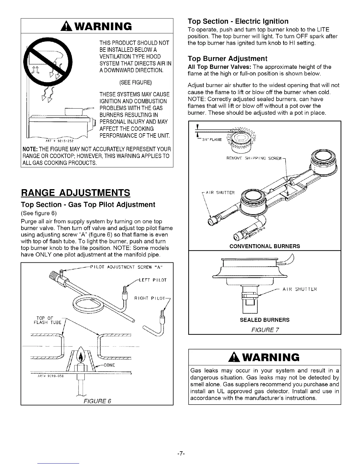
Top Burner Adjustment
All Top Burner Valves: The approximate height of the
flame at the high or full-on position is shown below.
Adjust burner air shutter to the widest opening that will not
cause the flame to lift or blow off the burner when cold.
NOTE: Correctly adjusted sealed burners, can have
flames that will lift or blow off without a pot over the
burner. These should be adjusted with a pot in place.
REMOVE SH PPI NG SCREWq _0_
CONVENTIONAL BURNERS
°1
#
[i
AIR SHUTTER
SEALED BURNERS
FIGURE 7
WARNING
Gas leaks may occur in your system and result in a
dangerous situation. Gas leaks may not be detected by
smell alone. Gas suppliers recommend you purchase and
install an UL approved gas detector. Install and use in
accordance with the manufacturer's instructions.
-7-
 Loading...