EN EN
Starter-blocking connection:
After cutting car starter lines, you have to connect lines to the relay outputs used to block
the starter.
2 – green - Ignition Input
- connect to the switchboard (to the +12V wire when ignition on).
3 – red/black
- Negative door switch input ( - )
4 – red
- Positive door switch input (+12V)
5 – orange/black
- Negative parking lights input (-). When switching on Magicar M871A this will indicate the
lights are on.
6 – orange
- Positive parking lights input (+). When switching on Magicar M871A this will indicate the
lights are on.
7 – grey/black
- Negative hood switch input (-)
8 – brown/black
- Negative trunk switch input (-)
9 –black/white
- Foot brake input reacting on (+)
7
- additional outputs
CONNECTOR 4 - red
Additional outputs controlled by the remote control. For
settings see programming menu 2-08, 2-09.
87 87a
86
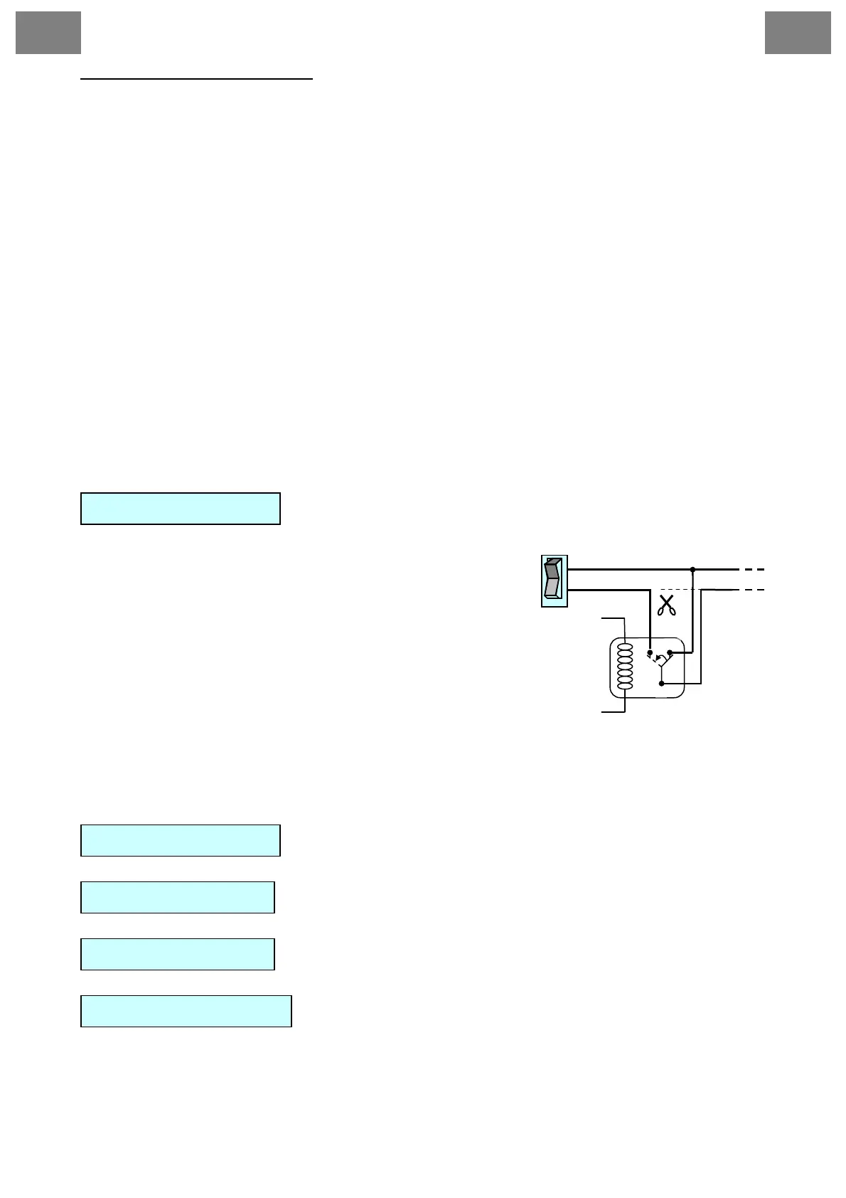
Switching circuit
+12V
AUX (-)
30
85
switch
Cutt off
• When connecting AUX, always check the power
supply, so it will not damage any equipment in the
car.
• When connecting AUX to electric windows you
must use an additional 12V relay.
If AUX is connected via the additional relay, use a 30A
fuse when connecting to the relay.
1 – yellow
- AUX1 output, rating capacity - 250mA.
2 – yellow/white
- AUX2 output, rating capacity - 250mA.
- Interface for Module CAN BUS MAGICAR
CONNECTOR 5 - black
CONNECTOR 6 - blue
- Antenna
CONNECTOR 7 - blue
- Temperature sensor
CONNECTOR 8 - white