Do you have a question about the Magicar M9000 and is the answer not in the manual?
Advise to lower windows before installation to prevent lockout when doors lock automatically.
Emphasize using a multimeter for all wire testing to prevent damage to electrical circuits.
Stress the importance of a clean, low-resistance ground connection for system reliability.
Ensure installation practices do not create hazards, such as wiring near brake pedals.
Recommend soldering all connections and properly insulating them with electrical tape.
Secure components properly and avoid damaging wiring from engine heat or vibration.
Proper wiring organization prevents noise, connection problems, and safety hazards.
Installer must thoroughly explain the system's operation to the end-user.
Verify all vehicle systems function correctly before and after the installation.
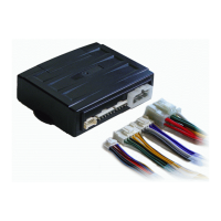
Details for CN1 including Accessory, Starter, Ignition, and Constant 12V power connections.
Explains CN2 connections for Signal Light, Door Unlock, and Door Lock outputs.
Details for CN3 including Siren, Trunk, and Starter-Kill outputs.
Covers CN4 for Temperature Sensor, Glow Plug, and Parking Light inputs.
Explains CN5 connections for the Dual Shock Sensor.
Details for CN6 connections for the Remote Pager Sensor.
Covers CN7 connections for the Antenna Module (RX, TX, Power).
Explains CN8 connections for AUX Output functionalities.
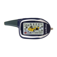
Procedure to enter valet mode by cycling the ignition key three times.
Pressing Button I to confirm valet mode entry and activate the controller relay.
Pressing Button I on the new remote within 3 seconds to teach it to the unit.
Specific instructions for Benz vehicles using Button III instead of Button I.
Specific instructions for propane gas vehicles using Button IV instead of Button I.
Steps for customizing system options using specific button press sequences.
Procedure to reset Menu #1 or Menu #2 to their original factory settings.
Highlights differences in programming menus between 6-button and 4-button remote units.
Details features like Diesel delay, signal light flash, and door lock output settings.
Covers configuration for Turbo, Hour Timer, and AUX output features.
Requires main module programming for utilizing Turbo and 24 Hr modes.
Indicates that three chirps signal a problem during the auto-start attempt.
Lists error numbers indicated by parking light flashes and their corresponding reasons.
Indicates the error code 1 means the engine is already running.
Indicates the error code 2 means the ignition key is in the ON position.
Indicates the error code 3 means a vehicle door is not properly closed.
Indicates the error code 4 means the vehicle trunk is not properly closed.
Indicates error code 5 for manual transmission vehicles when reservation is off.