10
CN2
9
No 1, No 2 (Violet) : Positive Signal Light Output
Connect this wire to the (+) signal light wire on the vehicle. This wire will read
(using your digital multi-meter) either open or ground before the signal light
circuit is turned on and then it will read (+)12V after the signal light circuit is
turned on.
No 3(Yellow) : Door Unlock Output
No 4(Green) : Door Lock Output
The following three door lock systems are the most common systems.
Relay
Diode
85
8630
87a
▼▼
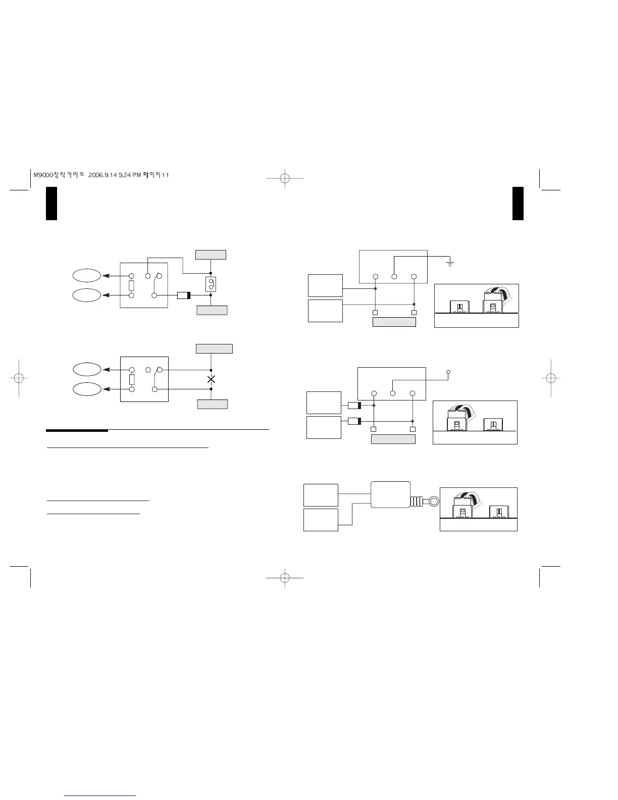
Method2 : Serial Connection with the switch
▼▼
Method1 : Parallel Connection with the switch
CN1-3
CN1-6
+12V power
Gas Valve SW
Gas Valve
87
Relay
85
8630
87a
CN1-3
CN1-6
Gas Valve SW
Cut
Gas Valve
▼▼
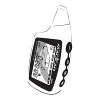
Method1 : Negative Trigger Door Lock System (W/O Actuator)
Door Connection
CN2-3(-)
Ulock
CN2-4(-)
Lock
EXT. (Positive) INT. (Negative)
▼▼
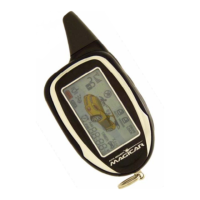
Method2 : Positive Trigger Door Lock System (W/O Actuator)
Door Switch
Factory Relay
Ulock
Lock
▼▼
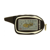
Method3 : External Actuator
Door Connection
CN2-3
Ulock
CN2-4
Lock
External
Actuator
EXT. (Positive)
INT. (Negative)
EXT. (Positive)
INT. (Negative)
Door Switch
Door Connection
CN2-3(+)
Ulock
CN2-4(+)
Lock
Factory Relay
Ulock
Diode
Lock
(+)12V