45-610 Displacer Type Liquid Level Switches and Proof-er
®
Switches
7
N
OTE: On high temperature applications above +250° F (+121° C),
high temperature wire should be used between control and
first junction box located in a cooler area. On non-hazardous
applications, flexible conduit may be used between the con-
trol and the first junction box.
6. Bring supply wires through conduit entry. Route extra wire
around enclosing tube under baffle plate, and connect
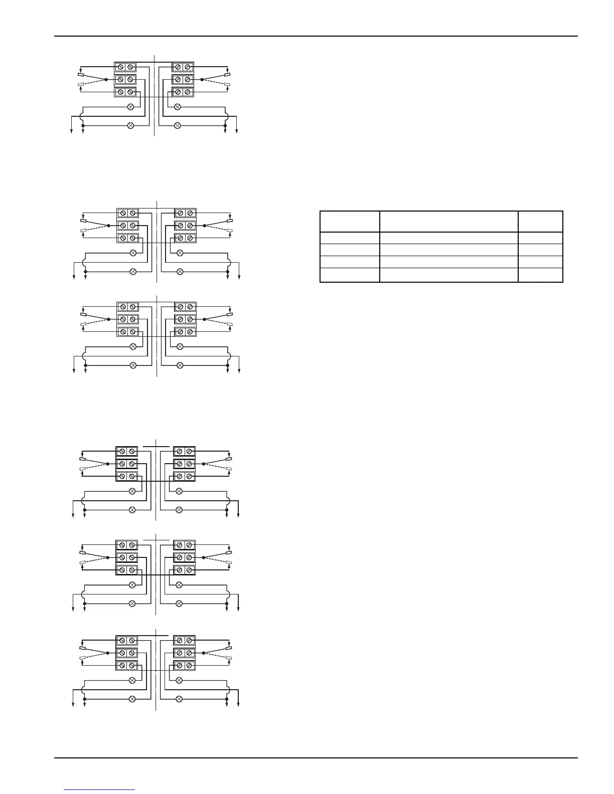
then to the appropriate terminals. Refer to Figures 4–9 for
wiring diagrams of Dry Contact Switch Series B, C, D, F,
O and Q only. For wiring diagrams for Series HS, J, and K
refer to the specific bulletin listed in the chart below:
NOTE: For models with a Series HS switch with high temperature
lead wire, the leads are routed out through the conduit open-
ing by the factory. A suitable conduit box should be provided
for the connection of the leads to the control wiring.
7. Dress wiring to ensure no interference or contact with tilt
of switch, or replacement of switch housing cover.
NOTE: Observe all applicable electrical codes and proper wiring
procedures.
Prevent moisture seepage into the enclosure by installing
approved seal-drain fittings in the conduit run leading into
the unit.
In hazardous areas, do not power the unit until the
conduit is sealed and the enclosure cover is screwed
down securely.
8. Test switch action by varying liquid level or manually
moving displacers.
9. Replace housing cover.
10. If control has been furnished with an explosion proof or
moisture proof (gasketed) switch housing, it must be
sealed at the conduit outlet with a suitable compound or
non-hardening sealant to prevent entrance of air.
NOTE: If switch mechanism fails to function properly, check vertical
alignment of control housing and consult installation bulletin
on switch mechanism furnished.
B, C, D, F, O, Q Dry Contact Switch 42-683
HS Hermetically Sealed Snap Switch 42-694
J Bleed Type Pneumatic Switch 42-685
K Non-Bleed Type Pneumatic Switch 42-686
I
NTERNAL
C
IRCUIT
(
RIGHT)
SWITCH
I
NTERNAL
C
IRCUIT
(
LEFT)
SWITCH
1
2
3
L
OAD
C
lose on high level (NO)
C
OMMON (C)
Close on low level (NC)
LINE
4
5
6
LOAD
C
lose on high level (NO)
C
OMMON (C)
Close on low level (NC)
LINE
LOAD LOAD
NOTES: 1. Double pole action is obtained by simultaneous operation of the
right and left side single pole switches.
2. Rising Level Closes Contacts 5 & 6 and 2 & 3.
3. Falling Level Closes Contacts 4 & 5 and 1 & 2.
I
NTERNAL
CIRCUIT
(RIGHT)
S
WITCH
I
NTERNAL
CIRCUIT
(LEFT)
S
WITCH
I
NTERNAL
CIRCUIT
(RIGHT)
SWITCH
I
NTERNAL
CIRCUIT
(LEFT)
SWITCH
1
2
3
LOAD
Close on high level (NO)
C
OMMON (C)
Close on low level (NC)
LINE
4
5
6
LOAD
Close on high level (NO)
C
OMMON (C)
Close on low level (NC)
LINE
LOAD LOAD
UPPER LEVEL RANGE OPERATES
UPPER SWITCH MECHANISM
1
2
3
L
OAD
C
lose on high level (NO)
C
OMMON (C)
Close on low level (NC)
L
INE
4
5
6
L
OAD
C
lose on high level (NO)
C
OMMON (C)
Close on low level (NC)
L
INE
L
OAD LOAD
L
OWER LEVEL RANGE OPERATES
LOWER SWITCH MECHANISM
N
OTES: 1. Double pole action is obtained by simultaneous operation of the
right and left side single pole switches.
2. Rising Level Closes Contacts 5 & 6 and 2 & 3.
3. Falling Level Closes Contacts 4 & 5 and 1 & 2.
I
NTERNAL CIRCUIT
(RIGHT) SWITCH
1
2
3
LOAD
Close on high level (NO)
COMMON (C)
C
lose on low level (NC)
LINE
4
5
6
I
NTERNAL CIRCUIT
(LEFT) SWITCH
LOAD
Close on high level (NO)
COMMON (C)
C
lose on low level (NC)
LINE
LOAD LOAD
U
PPER LEVEL RANGE OPERATES
UPPER SWITCH MECHANISM
I
NTERNAL CIRCUIT
(
RIGHT) SWITCH
1
2
3
1
2
3
LOAD
Close on high level (NO)
COMMON (C)
Close on low level (NC)
LINE
4
5
6
I
NTERNAL CIRCUIT
(
LEFT) SWITCH
LOAD
Close on high level (NO)
COMMON (C)
Close on low level (NC)
LINE
LOAD LOAD
M
IDDLE LEVEL RANGE OPERATES
MIDDLE SWITCH MECHANISM
INTERNAL CIRCUIT
(RIGHT) SWITCH
LOAD
Close on high level (NO)
COMMON (C)
Close on low level (NC)
LINE
4
5
6
INTERNAL CIRCUIT
(LEFT) SWITCH
LOAD
Close on high level (NO)
COMMON (C)
Close on low level (NC)
LINE
LOAD LOAD
LOWER LEVEL RANGE OPERATES
LOWER SWITCH MECHANISM
NOTES: 1. Double pole action is obtained by simultaneous operation of the
right and left side single pole switches.
2. Rising Level Closes Contacts 5 & 6 and 2 & 3.
3. Falling Level Closes Contacts 4 & 5 and 1 & 2.