5
51-646 Echotel
®
Model 961 & 962 Ultrasonic Level Switches
Figure 2
Typical Mounting Orientations
2.2 Electrostatic Discharge (ESD) Handling
Procedure
MAGNETROL electronic instruments are manufactured to
the highest quality standards. These instruments use
electronic components that may be damaged by static
electricity present in most work environments.
The following steps are recommended to reduce the risk of
component failure due to electrostatic discharge.
• Ship and store circuit boards in anti-static bags. If an anti-
static bag is not available, wrap the board in aluminum
foil. Do not place boards on foam packing materials.
• Use a grounding wrist strap when installing and removing
circuit boards. A grounded workstation is recommended.
• Handle circuit boards only by the edges. Do not touch
components or connector pins.
• Make sure that all electrical connections are completely
made and none are partial or floating. Ground all equip-
ment to a good, earth ground.
2.3 Mounting
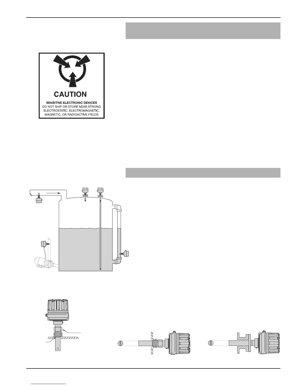
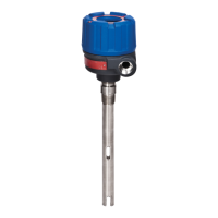
The Model 961 level switch may be mounted in a variety
of positions as shown in Figures 2 through 5. Model 962
is always mounted vertically.
Proper orientation of the transducer gap will facilitate
maximum performance in difficult applications. When the
Model 961 is mounted horizontally, the transducer gap
must be turned vertically to allow proper drainage of liquid
out of the gap. The wrench flats on the mounting nut are
aligned with the transducer gap; therefore, proper trans-
ducer mounting can be achieved by aligning the mounting
nut flats in a vertical orientation. See Figure 4. For flanged
transducers, a vertical gap orientation should be confirmed
prior to installing unit to the mating flange.
When installing a Model 961 switch in a nozzle or pipe,
the transducer gap must extend into the tank at least one
inch beyond the inside tank wall. Refer to Figure 5.
Screw transducer into the opening using a wrench on the
transducer mounting nut flats. If flanged, bolt unit to mat-
ing flange with proper gasket. Use thread tape or suitable
pipe compound on the threads. Do not over-tighten.
Pump
Protection
Fill Line
Dual Point Alarm
High Alarm
Low Alarm
Figure 3
Vertical Mounting
Use wrench on flats
Process
connection
Figure 4
Horizontal Mounting
Figure 5
Nozzle Mounting





 To Next Page