3
54-610 Thermatel Model TD1/TD2 Flow Level Switch
2.4 Wiring
The wiring connections for the power and relay are
suitable for 12–24 AWG wire.
Caution: OBSERVE ALL APPLICABLE ELECTRICAL CODES
AND PROPER WIRING PROCEDURES.
1. Make sure the power source is turned off.
2. Unscrew and remove housing cover.
3. Pull power supply and control wires through conduit con-
nection.
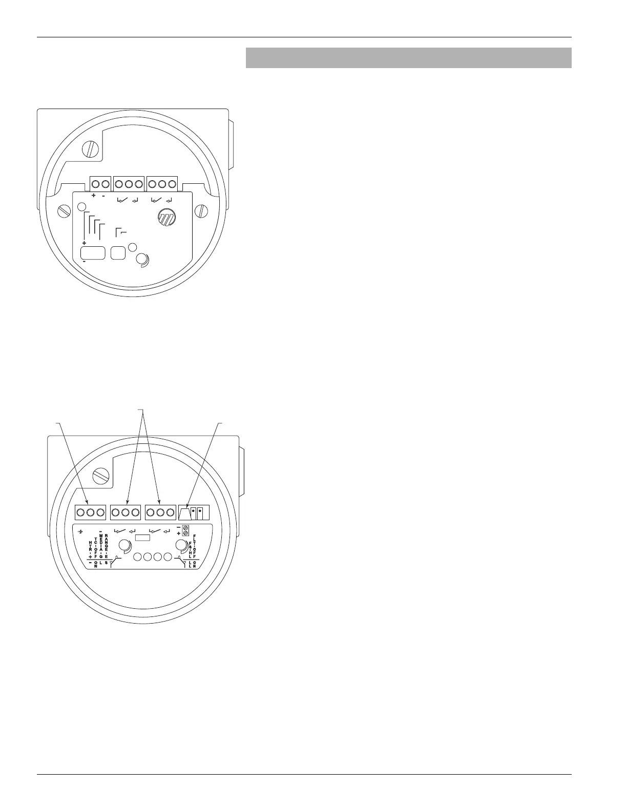
4. Connect power leads to proper terminals. Refer to Figure 6
for TD1 or Figure 7 for TD2 electronics. Note that the
TD1 is only available with 24 VDC input power. The
TD2 is available for AC power (100 to 260 VAC) or as a
DC power (19.2 to 28.8 VDC).
a. AC power – Connect “hot” wire to terminal marked L1
and the “neutral” wire to the terminal marked L2/N (TD2
Only). The green screw should be used for grounding.
b. DC Power – Connect wires to terminals (+) and (-) on the
terminal block. Unshielded cable can be utilized.
5. Perform Relay Connections (refer to Figure 6 for TD1 or
Figure 7 for TD2 electronics).
6. Prevent moisture seepage into housing by installing an
approved seal drain fitting in the conduit run leading to
the unit.
7. Installation is complete. Replace housing cover.
Caution: In hazardous areas, do not power the unit until the
conduit is sealed and enclosure cover is screwed
down securely.
NOTE: For supply connections use wire with a minimum rating of
+75° C, as required by process conditions. Use a minimum of
12–16 AWG wire for power and ground field wires.
NOTE: An approved disconnect device and current limiting device or
circuit breaker, maximum 15A shall be installed in close prox-
imity to equipment and within easy reach of operator.
It shall be marked as the disconnecting device for the equip-
ment.
NOTE: Housing must be grounded via protective ground screw in the
base of the housing.
Figure 6
TD1 Wiring
Figure 7
TD2 Wiring
 Loading...