6
54-610 Thermatel Model TD1/TD2 Flow Level Switch
2.5 Setup
2.5.1 Switch Settings
The TD1 and TD2 have a series of switches which may
require field adjustment depending upon the application.
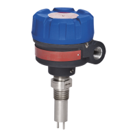
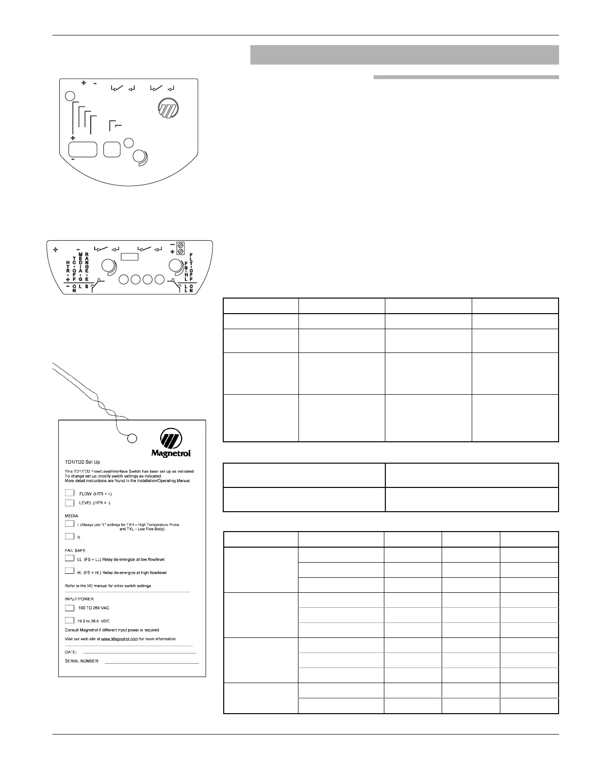
Switch position for the TD1 is shown in Figure 9 and
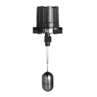
switch position of the TD2 is shown in Figure 10.
There are two sets of switches on the TD1/TD2. One set
has 4 switches, the second set has two switches.
The switch settings are set at Magnetrol during setup.
Changes in the positions may be required in the field
depending upon the application. There is a tag wired onto
the switch which indicates the default settings. See
Figure 11. Use the following table for recommended
switch settings.
Switch Purpose Options
Heater Control heat to sensor See sensor table below Default is “+”
Temperature
Compensation
ON/OFF See sensor table below Default is “on”
Media Gas/liquid Select
Default is liquid “L”
Use gas “G” position
only for gas flow
applications
Range
Expand sensitivity for
water flow applications
Switch to “E” position
for water flow
applications to
improve sensitivity
Default is “S”
Sensor Application Heater TempComp Media
Spherical Tip
(TXA, TXB)
Liquid Flow
+
on L
Gas Flow
+
on G
Level
-
on L
Twin Tip
(TXG, TXD)
Liquid Flow
+
on L
Gas Flow
+
on G
Level
-
on L
HTHP
(TXH)
Liquid Flow
+
on L
Gas Flow
+
on L*
Level
-
on L
Flow Body
(TXL)
Liquid Flow
+
on L
Gas Flow
+
on L*
Fail-safe
HL = High Level Fail-safe
LL = Low Level Fail-safe
Fault detection
Should be on (some applications may require
that this be turned on, see Section 3.4).
Four-position Switch
Two-position Switch
Sensor
Figure 9
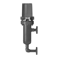
TD1 Connections
Figure 10
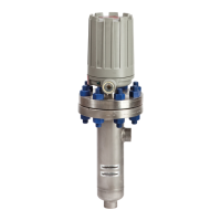
TD2 Connections
Figure 11
TD1/TD2 Set-up Tag
 Loading...