Operation Manual
touchTymp MI 24
and
MI 34
Version
4.2.2 Connections for Accessories, Power Supply and USB-Devices
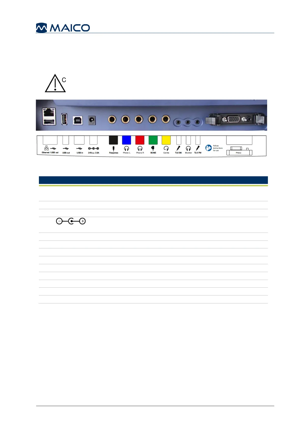
Figure 16 shows the connections on the backside of the device. The connections are
explained in Table 3.
Insert plugs with care into the appropriate connection. Do not
wiggle the plug or pull with force while connected. Disconnect
plugs cautiously. Consider instructions for Changing the Probe
System given in this section.
Figure 16
Table 3 Connections on Backside of Device
Dual connector: Ethernet – no function in actual touchTymp
version / USB A-connection for connection of USB flash drive
USB A-connection for connection of USB flash drive
USB B-connection for data transfer to PC
Power socket for power supply Item no. 8101895
Connection for the Patient Response Switch
Connection for Headphones Left
Connection for Headphones Right
No function in MI 24/MI 34 versions
Connection of Contralateral headphone
No function in MI 24/MI 34 versions
No function in MI 24/MI 34 versions
No function in MI 24/MI 34 versions
See section 6.3 for more information on the pin assignment.
1 2 3 4 5 6 7 8 9 10 11 12
13
 Loading...