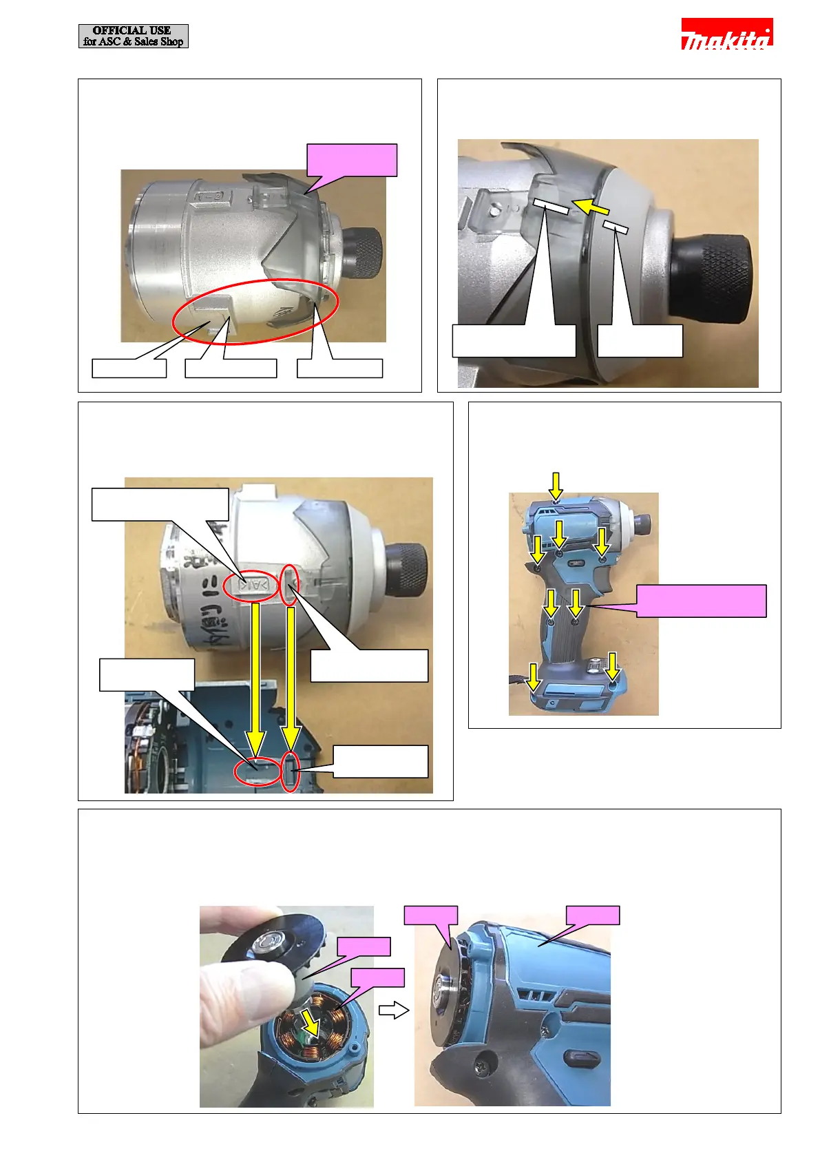
[9] Insert Rotor into Stator.
Note:
· Be careful not to pinch your fingers between Fan and Housing because Rotor has strong magnetic force.
· Once Rotor has been inserted, do not force it into Stator any further or you will break Controller print board.
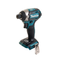
[6] Assemble Bumper to Hammer case cover while
aligning each groove.
[5] Assemble Hammer case cover to Hammer case
complete as shown below.
Groove on Hammer
case cover
[8] Assemble Housing R to Housing L with eight
Bind PT 3x16 Tapping screws.
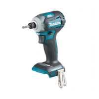
[7] Assemble Hammer case complete to Housing L by aligning
the projection on Hammer case complete and claw on
Hammer case cover with the grooves on Housing L.
Bind PT 3x16 Tapping
screws (8 pcs.)
Projection on Hammer
case complete
Claw on Hammer
case cover
8 / 19
 Loading...