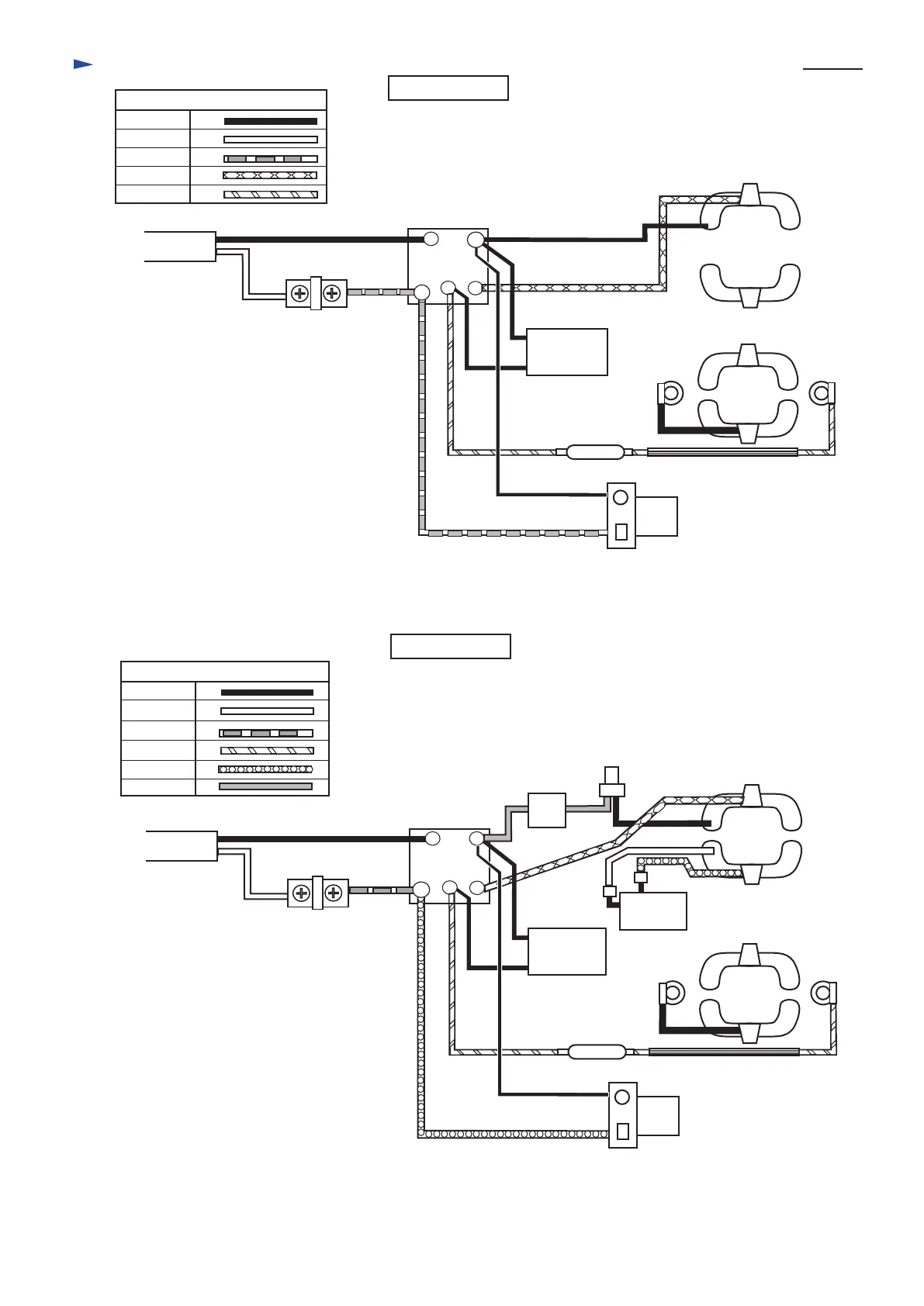
Circuit diagram
P 7 / 8
Color index of lead wires
Black
White
Red
Orange
Yellow
Field
(view from armature fan side)
Field
(view from commutator side)
For low voltage
For high voltage
Color index of lead wires
Black
White
Red
Orange
Purple
Gray
1
2
5
Switch
Terminal
block
Light assembly
Choke coil
Field
(armature fan side)
Field
(commutator side)
1
2
4
5
Switch
Terminal
block
Light assembly
Choke coil
3
4
* For some countries, the products can
be supplied without installing terminal
block and noise suppressor .
* For some countries, the products can
be supplied without installing choke
coil.
In this case, field is connected directly
to switch terminal No.2 with orange
lead wire.
* For some countries, the products can
be supplied without installing terminal
block soft starter circuit and noise
suppressor .
* For some countries, the products can
be supplied without installing choke
coil.
In this case, field is connected directly
to switch terminal No.2 with orange
lead wire.
Noise
suppressor
3
Noise
suppressor
Soft starter
circuit
Switch
for brake

 Loading...