20
ITALIANOENGLISH
20
ITALIANOENGLISH
Injector
• Follow the wire coming out of the
injector and cut it at about 3 cm
from the connector, as shown in
Fig. 2.
• Connect the female faston 1
supplied into the kit to the original
connector 2 by using the joint 3,
and carefully respecting the colours
of the wires (Fig. 3).
Attention: carefully check the
colour of the cables according to
your vehicle.
NB: pay attention to use the FEMALE
faston (1 - Fig. 3)!
• Close the joint using a pliers, such
as shown in Fig. 4.
• At this point connect the male
faston 4 to the wiring of the vehicle,
using the joint as shown in Fig. 5.
Cables must be connected strictly
in accordance with the colours
shown in Fig. 3.
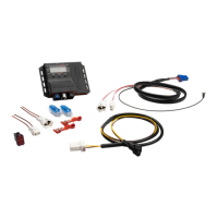
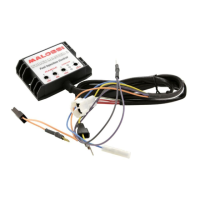
• Connect the control unit to the two
previously prepared connectors
(Fig. 6).
Ground
• Connect the black cable 5 (negative
pole) coming out of the Malossi
control unit to the screw as shown
(Fig. 7).