ITALIANOENGLISHFRANÇAIS
8
Technical details
• Carburetion adjusting
• at min/medium/max
• RPM limiter shifted to
RPM
• dierent maps:
» Curve 0: original twin-
cylinder, original camshaft,
Malossi exhaust system,
Malossi air ilter
» Curve 1: Malossi pistons
Ø, Malossi camshaft,
Malossi exhaust system,
Malossi air ilter
» Curve 2: Malossi twin-
cylinder Ø, original
camshaft, Malossi exhaust
system, Malossi air ilter
» Curve 3: Malossi twin-
cylinder Ø, Malossi
camshaft, Malossi exhaust
system, Malossi air ilter
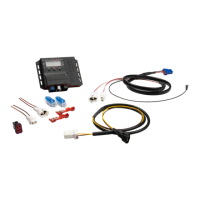
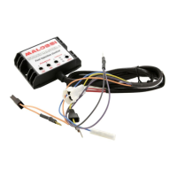
Assembly instructions
CDI assembly
• Place the Force Master 2 CDI
under the seat (Fig. 3) and
run the wires to the engine,
taking care that they will not be
damaged.
• Connect the electrical tap
included into the Malossi
kit to the yellow wire of the
connector located on the
throttle body
(Fig. 2 - Fig. 5, point .
• Connect the yellow wire
which comes from the CDI to
the electrical tap connector
(Fig. 5, part. 1).
WARNING
Once the wire is connected to
the electrical tap connector we
suggest to tape the wire bunch,
to avoid electrical tap vibrations
damaging the wires.
• Disconnect the injector and
connect it to the two pairs of
connectors on the Malossi CDI
(Fig. 6).
• Connect the black wire
negative pole which comes
from the Malossi CDI on the
engine in the variator cover.
(Fig. 4).
• Locate the SMALL faston
orange wire connected to the
original coil and disconnect it
(Fig. 1-A / 1-B).
• Insert the faston which comes
from the Malossi ECU orange
wire to the original coil.
• Connect the original wire to
the ECU’s bypass to complete
the circuit (Fig. 1-A / 1-B).
• Fix the CDI.