ITALIANOENGLISHFRANÇAIS
9
TPS (Throttle Position
Sensor) Calibration – Fig. 7
Insure the run switch is in the run
position and that the side stand is
up the scooter needs to be in the
running condition.
• Rotate the “LOW” trimmer to
the red arrow position.
• Turn the ignition key to the
“ON” position.
• Wait for all three (3) LEDs to
illuminate and then wait for
them to turn o.
• Turn the ignition key to the
“OFF” position.
• Rotate the “LOW” trimmer to
the “ZERO (0)” position.
• Rotate the “HIGH” trimmer to
the red arrow position.
• Turn the throttle to the fully
open position.
• Turn the ignition key to the
“ON” position.
• Wait for all three (3) LEDs to
illuminate and then wait for
them to turn o.
• Turn the ignition key to the
“OFF” position.
• Rotate the “HIGH” trimmer to
the “ZERO (0)” position.
If the red LED starts blinking while
calibrating the MIN and MAX,
this means that procedure has
not been carried out correctly
and that the throttle was not
positioned correctly. In this
case, re-do the TPS calibration
procedure from the start.
WARNING
If one of the three trimmers is
positioned on a red arrow then
the vehicle will not start.
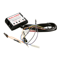
Diagnostics
The ECU has three (3) dierent
colored LEDs (Fig. 7):
• RED:
indicates a damaged ECU. A
damaged ECU is indicated if
the red LED illuminates while
the vehicle is running.
The principal causes for this
problem are:
Battery voltage too low or
too high.
Fuel injection cable is
damaged due to interference
with the frame
Damaged ECU.
• AMBER:
indicates the trimmers have
been adjusted correctly.
• GREEN:
indicates the ECU is