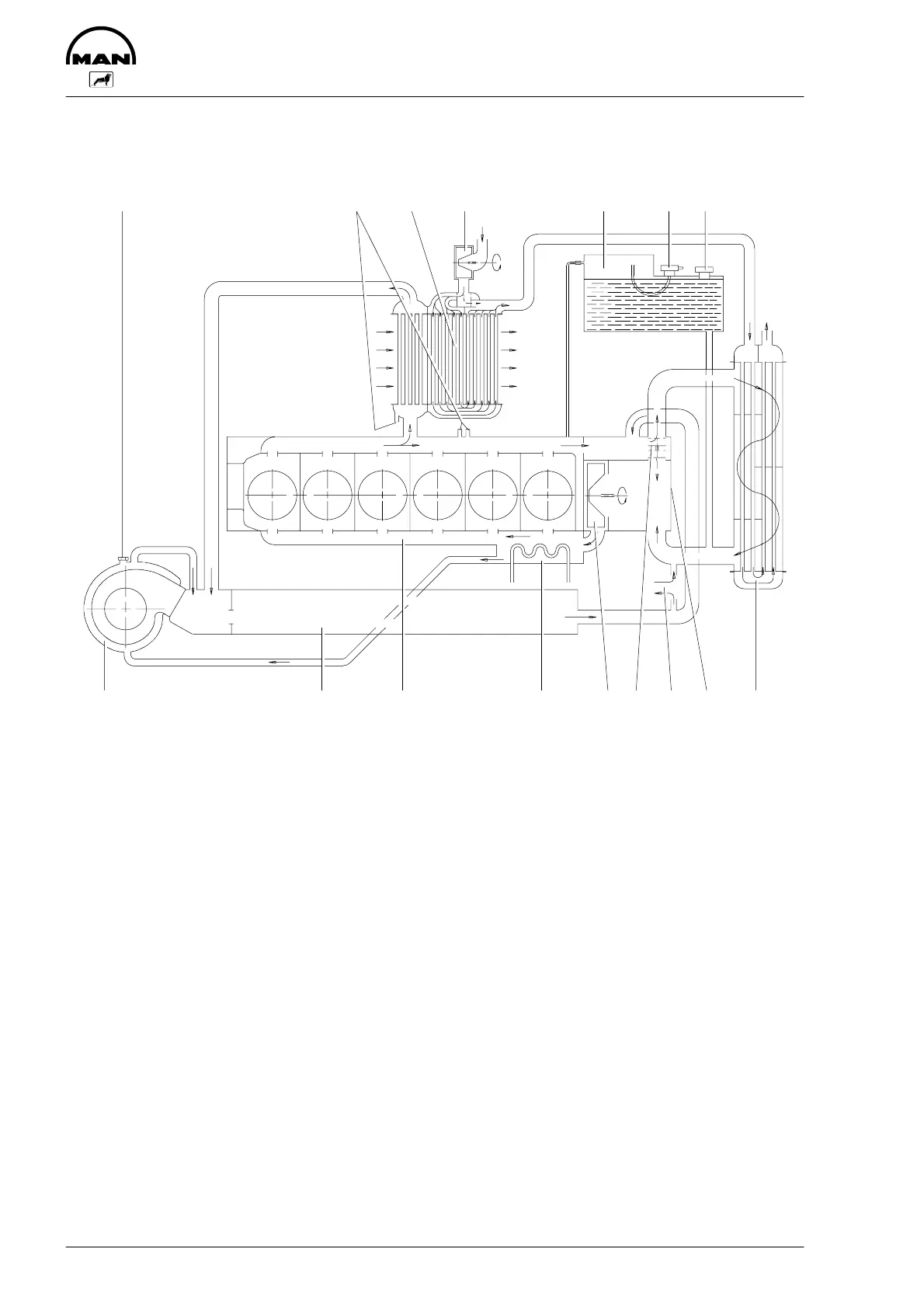
Schematic diagram of cooling system
22
9
1234576 8
10 111514 13
12
16
2583
1 Water pump housing with 9 Expansion tank
integrated thermostat housing 10 Over/underpressure valve
2 Water pump impeller 11 Coolant filler neck
3 Engine oil cooler 12 Heating lead and return line
4 Crankcase 13 Measuring point for cooling water temperature
5 Exhaust manifold, liquid-cooled 14 Bleed screw on turbocharger
6 Turbocharger, liquid-cooled 15 Raw water pump
7 Thermostat 16 Intercooler
8 Engine coolant/raw water heat exchanger
 Loading...