5
6
Setting valve clearance
85
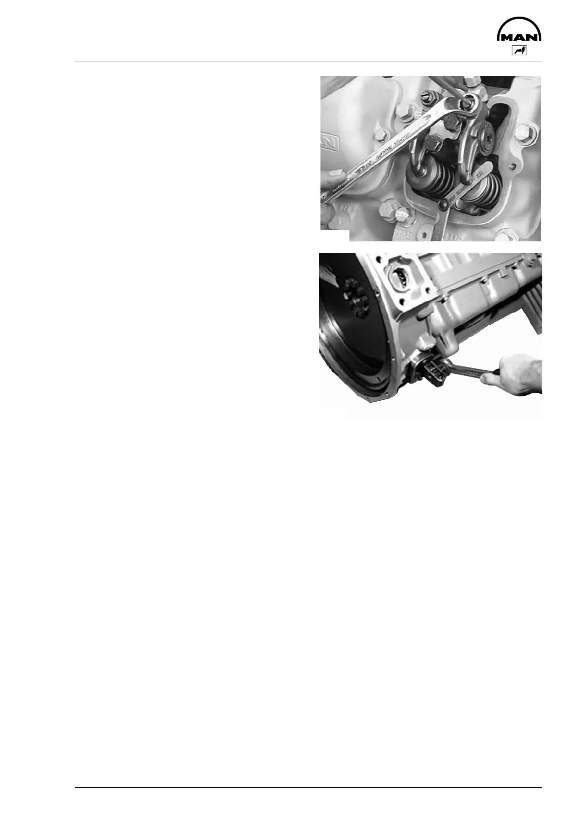
Fig. 5
Push feeler gauge between valve stem and rocker
arm. Loosen lock nut (17 mm) and turn adjusting
screw with screwdriver until feeler gauge can be
moved with slight resistance.
Tighten lock nut to the specified torque (see
”Engineering S Data S Setting values”) using screw-
driver to prevent adjusting screw from turning.
Check clearance again.
Refit cylinder head covers.
Fig. 6
If the inspection hole on the flywheel housing is
accessible, a device with ratchet (special tool) may
be attached there for turning the engine over.
3608
3392
 Loading...