J
Jamie BakerAug 20, 2025
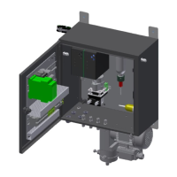
What to do if M&C Analytical Instruments cooler alarm registers ‘excess temperature’?
- JJames DixonAug 20, 2025
If the cooler alarm registers ‘excess temperature’, check if the supply voltage plug is correctly inserted and if the main switch is in the ‘I’ position. The cooler might be turning the gas measuring pump off automatically.