EasyManua.ls Logo

M&C PSS Series - User Manual

M&C PSS Series
48 pages
Print Icon
To Next Page IconTo Next Page
Loading...
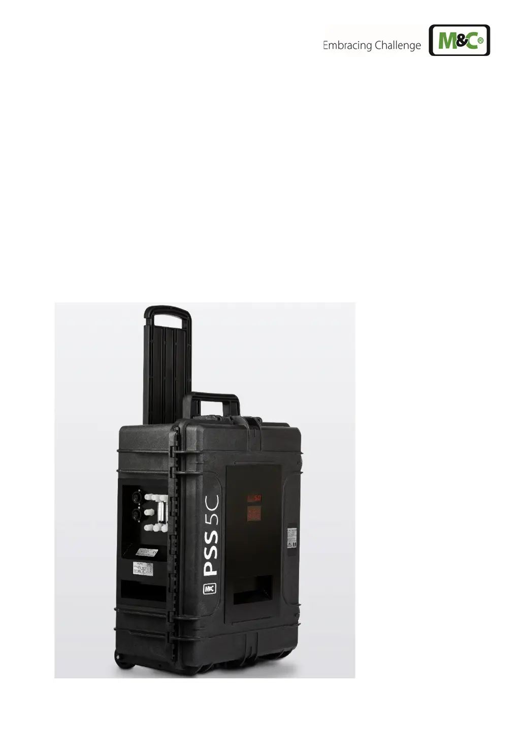
Portable Gas Conditioning Unit Series
PSS
®
PSS-5C, PSS-5/2C, PSS-5/3C
Instruction Manual
Version 1.02.02

Table of Contents

Questions and Answers

  • L
    Lucas GrossSep 13, 2025
    Why is there condensate in the sample gas lead of my M&C Test Equipment, even when the cooler and gas pump are running?
    • V
      vwilsonSep 13, 2025
      If you observe condensate in the sample gas lead while the cooler and gas pump are running on your M&C Test Equipment, the pre-filter might be clogged. Remove the filter from the condensate lead to resolve this. Another potential issue is a faulty pump hose, which requires a filter change. Inadequate drying of the sample gas can also cause this; in that case check the cooler. If you have an optional liquid alarm sensor, confirm that it is functioning correctly and has turned the pump off when necessary; if not, inspect the LA electronics and replace them if needed.
  • A
    Ashley BurchSep 18, 2025
    What to do if there is condensate in the sample gas line of M&C Industrial Equipment?
    • C
      Charles TateSep 18, 2025
      If the cooler and sample gas pump are running, but there's condensate in the sample gas line of your M&C Industrial Equipment, check the LA sensor function. Also, the issue might stem from insufficient drying of the sample gas.
  • M
    michaelwoodsDec 1, 2025
    What to do if the sample pump of my M&C PSS Industrial Equipment does not start?
    • H
      hayselizabethDec 1, 2025
      If the sample pump of your M&C Industrial Equipment does not start, there could be several reasons: * A diaphragm pump failure: remove the gas lines from the pump head and check it. * Diaphragm pump contamination: clean the pump as needed. * Blocked or compressed gas sample probe/gas line: remove the gas tubing from the gas inlet. * Blocked or compressed sample gas line connected to the analyzer: clean or change the gas way. * The sample pump switch is not turned on: open the sample gas pump switch. * Humidity sensor contact switch to close the sample pump: check the peristaltic pump discharge. * Also, check the condensate discharged from the tube, the filter (replace the filter element in time and dry the filter chamber if the inside is wet), the cooler (according to the in...

Summary

Safety Instructions and Warranty

General Safety Procedures

Basic safety procedures for mounting, starting up, and operating the equipment.

Technical Data and Specifications

Product Model Specifications

Lists technical data for PSS-5C, PSS-5/2C, PSS-5/3C including part numbers and operating parameters.

Operating Environment

Defines the operational temperature range, storage temperature, and pressure limits for the device.

Operating Instructions

Main Menu Navigation

Explains how to navigate the main menu of the ECPX000C controller and view system status.

Menu Navigation Diagram

Visually demonstrates the process of navigating through the device's main menu interface.

PIN Entry Procedure

Set Point Entry and Adjustment

Parameter Setting and Code Entry

Parameter Setting and Code Entry

Explains how to enter parameter codes to adjust device settings.

Temperature Alarm Limit Configuration

Alarm Limits and Hysteresis Diagram

Diagram illustrating temperature alarm limits (HIGH dT, LOW dT) and hysteresis settings.

mA Output Configuration and Calibration

mA Output Calibration Procedure

Details the process for calibrating the mA output for temperature measurement, covering factory and retrofitted units.

Liquid Alarm Sensor (LA1 S) Operation

Liquid Alarm Sensor Sensitivity Adjustment

Liquid Alarm Sensor Calibration

Installation Instructions and Site Requirements

Installation Instructions and Site Requirements

Details proper installation procedures, environmental requirements, and operational positioning.

Supply Connections and Tube Fittings

Tube Connection Details

Details the tube connections for sample gas, condensate, and power supply, including fitting types and materials.

Medium Connection Diagram

Diagram showing the medium connections located on the rear of the gas conditioning case.

Connecting Heated Sample Lines

Electrical Connections Overview

Electrical Connection Overview

Details electrical connection warnings and notes for power installations.

Electrical Connection Points and Options

Electrical Connection Diagram

Depicts the electrical connections on the unit, labeling power, heated sample line, and mA output connectors.

Commissioning Procedure and Safety Checks

Initial Commissioning Steps

Guides through connecting power, heated lines, and setting the temperature controller.

Maintenance Procedures and Safety Precautions

General Maintenance Warning

Emphasizes safety precautions, especially regarding dangerous voltage, before performing maintenance.

Troubleshooting Common Issues

Gas Flow Interruption Problems

Addresses issues related to gas flow interruption, including E5 error codes and pump malfunctions.

Cooler Issues with Interrupted Gas Flow

Troubleshoots problems when the cooler works but gas flow is interrupted, checking sample lines and pumps.

Troubleshooting Pump and Condensate Issues

Cooler and Pump Running Problems

Addresses issues where the cooler and sample gas pump are running, but there's no output or condensate presence.

Parameter Code Reference

M&C PSS Series Specifications

General IconGeneral
Power SupplyAC/DC
Operating Temperature-20°C to +70°C
Protection FeaturesOvertemperature, overcurrent
DimensionsVaries depending on model (compact to larger sizes available)
CertificationsCE