V.033114
14 M&R Companies 1N 372 Main St. Glen Ellyn, IL 60137 USA
Tel: +630-858-6101 Fax: +630-858-6134 www.mrprint.com | store.mrprint.com
6. Operation
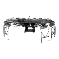
Yellow Cycle Interruption Cords are provided to restrict
access into the index table operating area while the
equipment is in operation. To disconnect, grasp each of the
cords at the magnetic jack connection and pull apart.
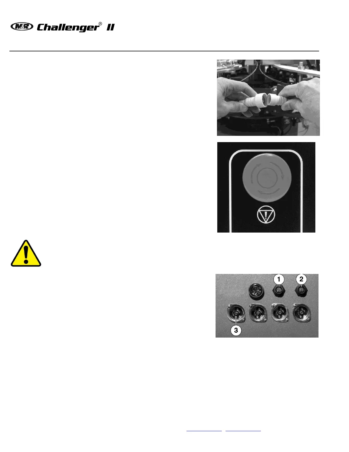
The red EMERGENCY STOP Button is provided to stop all
operation of the equipment in an EMERGENCY situation.
Push the button to activate.
WARNING: Do NOT turn off electrical power until all Flash Cure Units have cooled down to 38 C
(100 F) or lower.
Accessory Sockets are located on the lower electrical
enclosure.
(3-Pin) No Shirt Detector Cable (1)
(2-pin) Foot Pedal Control Cable (2)
Flash Cure Signal Cable (3)
Note: Socket location, number and type vary by options ordered
and machine model.