Place the switch for the rear screen frame clamps
on the print head control panel in the OFF
position. This allows the screen frame to move
freely during micro-register adjustments.
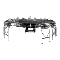
Check the micro-register adjustment knobs to be
sure that they are not binding. The knobs should
have slight play (1/32”) in both the clockwise and
counterclockwise directions.
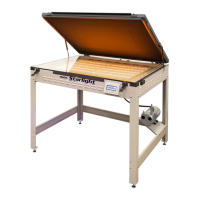
Unlock both the right and the left micro-register
locking handles.
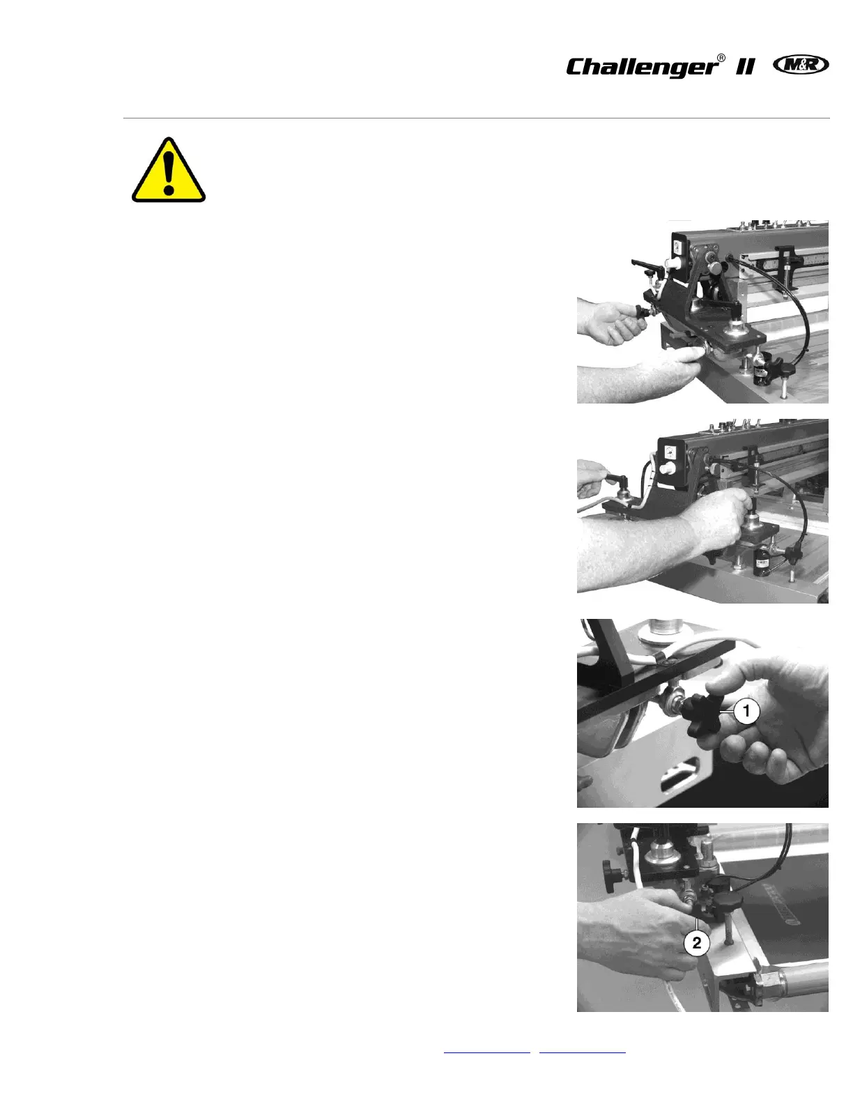
The two micro-register knobs (1) at the front of the
screen frame holder assembly are used to move
the screen frame from the front to the rear. The
micro-register knob (2) on the right side of the
screen holder assembly is used to move the
screen frame from the left to the right.
The micro-register adjustments allow for
movement of 1/4” from the zero or center position
for an overall range of 1/2” right to left and front to
rear.
When you have completed the micro-register
adjustments, check to be sure the adjustment
knobs still have the 1/32” play in both the
clockwise and counter clockwise directions. Now
lock the micro-register locking handles securely.
Place the switch for the rear screen frame clamps
on the print head control panel in the ON position.
 Loading...