V.033114
56 M&R Companies 1N 372 Main St. Glen Ellyn, IL 60137 USA
Tel: +630-858-6101 Fax: +630-858-6134 www.mrprint.com | store.mrprint.com
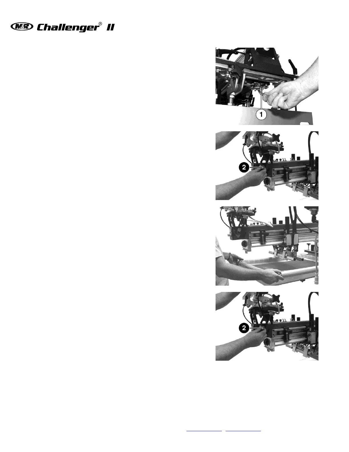
For easy installation of screen frames, and/or
flash cure units, the M&R print stations feature a
Flip Up Front Frame Holder which pivots up and
out of the way. To move the front frame holder up
to the load position, unlatch the front frame holder
lock handle (1). To unlatch, push the locking
handle lever down.
Move the front frame holder up to the lock
position. A spring loaded locking pin (2)
automatically secures the front frame holder in
place during screen frame or flash unit installation.
Install screen frame in the rear screen frame
holder. Place the REAR FRAME LOCK switch on
the print head control panel in the ON position.
The pneumatic cylinders lock the screen frame
into the screen frame holder. To release the
screen frame, move the switch to the OFF position
and remove the screen frame from the screen
frame holder.
Pull out the locking pin knob (2). Move the front
screen frame holder to down into the print
position.