3-47
1 m
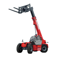
G6/1
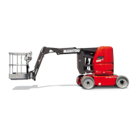
G6 MAINTENANCE STAND
USE
If you have to make repairs to the arms, the turret, the engine, etc.
Follow the instructions below:
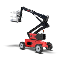
- From the base console, order the lower arms to rise until the upper joint is 1m above the
counterweight (Fig. G6/1).
MACHINES WITHOUT MAINTENANCE STAND
- Place a sling connected to a hoist on the upper joint 1 (Fig. G6/1).
- From the base console, order the lower arms to lower until the belt is taut: then immediately
release the controls.
- Switch off the engine and cut the power to the platform using the battery cut-out.
- Make the necessary repairs....
MACHINES WITH MAINTENANCE STAND
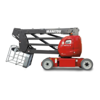
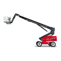
- Loosen the lock nut 2 (Fig. G6/2)
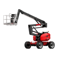
- Climb onto the back part of the chassis (beside the counter-weight), remove the maintenance
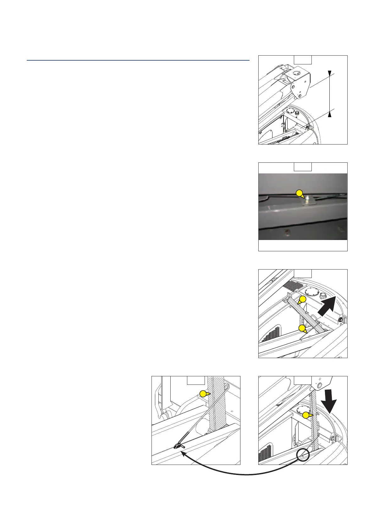
stand 3 (Fig. G6/3) manually and insert the holding bracket 4 (Fig. G6/3); take care to lock this
(Fig. G6/4).
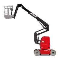
- From the base console, order the lower arms to lower until the upper joint is in contact with the
maintenance stand (Fig. G6/4 and G6/5): then immediately release the controls.
- Switch off the engine and cut the power to the platform using the battery cut-out.
- Make the necessary repairs...
After these operations, follow the instructions below:
MACHINES WITHOUT MAINTENANCE STAND
- From the base console, order the lower arms to rise until the belt is loose: release the controls.
- Remove the sling from the upper joint, put the lifting platform in Transport position and switch
off the engine.
MACHINES WITH MAINTENANCE STAND
- From the base console, order the lower arms to rise by 20cm: release the controls.
- Climb onto the chassis, remove the maintenance stand retaining bracket and then lower it (Fig.
G6/3).
- Put the lifting platform in Transport position and switch off the engine.
G6/2
G6/3
G6/4G6/5
2
4
3
1
1
647400 EN (01/02/2015)
 Loading...