30
3
MHT 10120 L M
Series
Place a container large enough for the quantity of liquid to be col-
lected, under the radiator drainage screw “4” (Fig. F4/4).
Unscrew the radiator drainage screw “4” (fig. F4/4) (in the lower
part of the radiator) and drain out the cooling liquid.
Clear the drainage opening of obstruction, if present.
Tighten the cooling liquid drainage screws present on engine “3”
(Fig. F4/3) and on radiator “4” (Fig. F4/4).
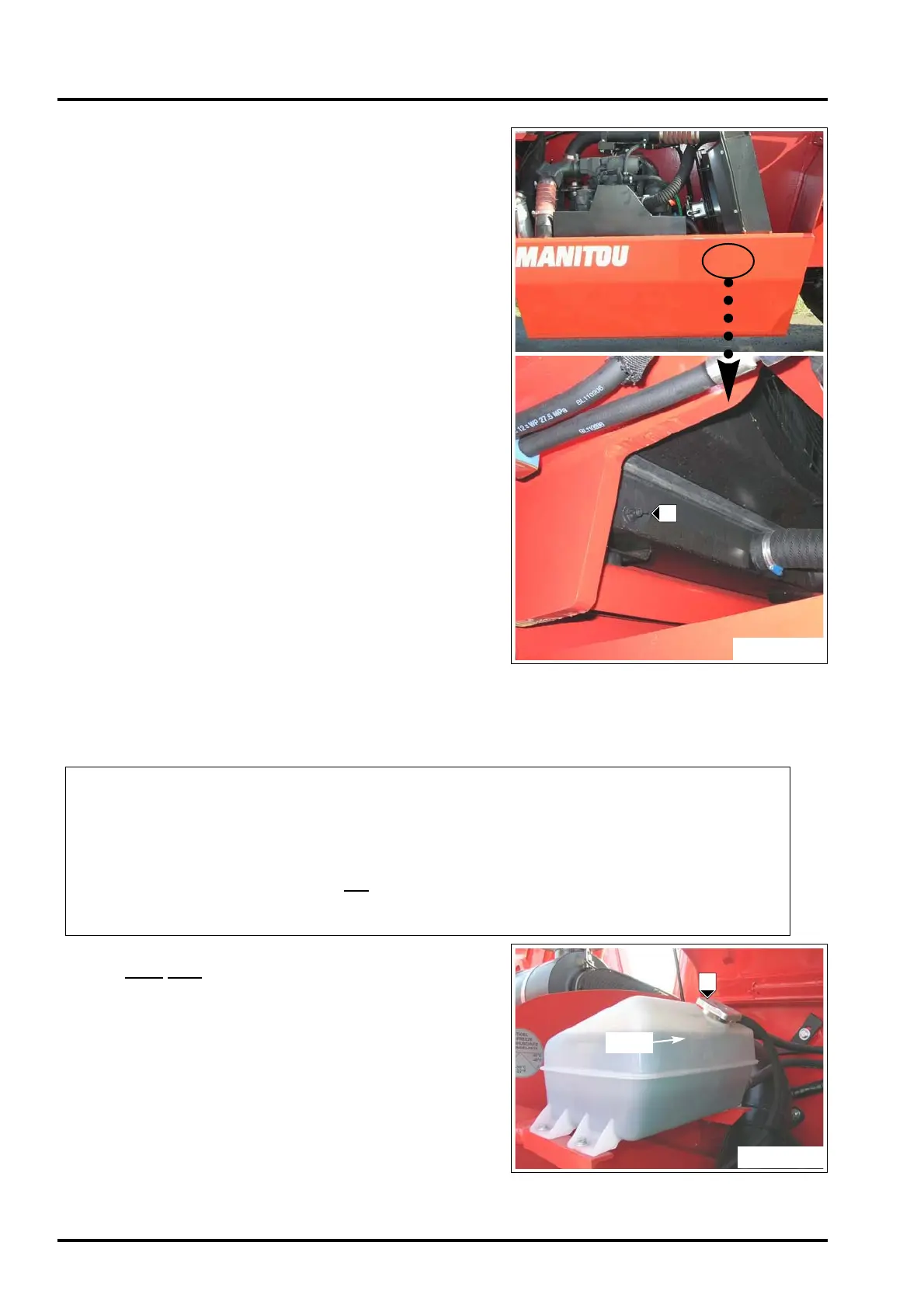
Filling the cooling system
Before filling the cooling system, prepare the liquid to be filled
according to the water and cooling liquid percentages indicated in
the Table (F4/5).
Pour the cooling liquid through the opening in tank “5” (Fig. F4/6)
up to the MAX.
mark.
Refit cap “5” to close the tank (Fig. F4/6).
Start up the engine and run it for about one minute, changing
the speed to release air bubble from the cab cooling and hea-
ting system.
Switch the engine off and top up with cooling liquid to the MAX
level in the tank.
TABLE (F4/5)
FREEZING POINT DEPENDING ON THE % VOLUME OF ANTIFREEZE AND WATER
Antifreeze Water Temperature
SHELL ANTIFREEZE (distilled recommended) freezing
25% 75% -10 °F
35%
65%
-6 °F
40% 60% -15 °F
50% 50% -36 °F
FIG. F4/4
4
FIG. F4/6
5
MAX
 Loading...