5
7
MHT 10120 L M
Series
ENGAGING THE ACCESSORY
- Check that the accessory is in a position which simplifies connection
of the snap coupling. If it is badly positioned, take the necessary pre-
cautions to move it in the conditions of maximum safety.
- Check that the rods of the locking cylinder are retracted.
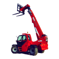
- Position the lift-truck with the boom lowered squarely in front of and
parallel to the accessory and tilt the snap coupling forward (Fig. A).
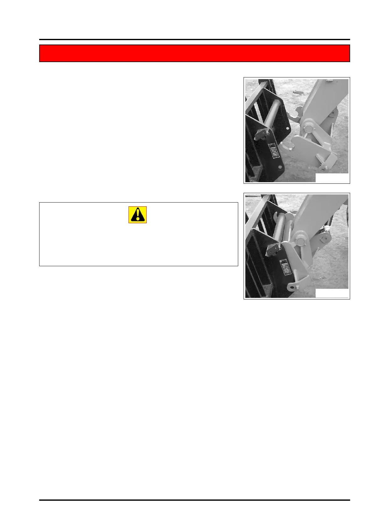
- Bring the snap coupling into position below the accessory’s connec-
tion pipe, raise the boom slightly and tilt the connection back to posi-
tion the accessory (Fig. B).
- Raise the accessory off the ground for easier engagement.
HYDRAULIC LOCKING AND RELEASE (OPTIONAL)
- The accessory (if any) is locked and released using the optional con-
trol (which may be operated by a push-button or using the control
lever itself, depending on the type of truck). For further information,
refer to the use and maintenance manual provided with the truck.
Remember to decompress the optional circuit whenever
an extra accessory is to be connected to or
disconnected from the lift-truck; this will simplify the
engagement and disengagement of the snap
couplings on the end of the boom.
REMOVING (AND PUTTING DOWN) THE ACCESSORY
- Proceed in reverse direction to the ENGAGING THE ACCESSORY
procedure, taking care to place it in a safe position on firm, flat
ground.
ACCESSORY WITH HYDRAULIC SYSTEM AND HYDRAULIC LOCKING (OPTIONAL)
ACCESSORY WITH HYDRAULIC SYSTEM AND HYDRAULIC LOCKING (OPTIONAL)
Fig. A
Fig. B
 Loading...