4
5
MHT 10120 L M
Series
ENGAGING THE ACCESSORY
- Check that the accessory is in a position which simplifies connection
of the snap coupling. If it is badly positioned, take the necessary
precautions to move it in the conditions of maximum safety.
- Check that the locking pin is engaged in the support provided on the
frame.
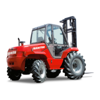
- Position the lift-truck with the boom lowered squarely in front of and
parallel to the accessory and tilt the snap coupling forward (Fig.A).
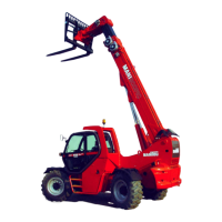
- Bring the snap coupling into position below the accessory’s connec-
tion pipe, raise the boom slightly and tilt the connection back to posi-
tion the accessory (Fig.B).
- Raise the accessory off the ground for easier engagement.
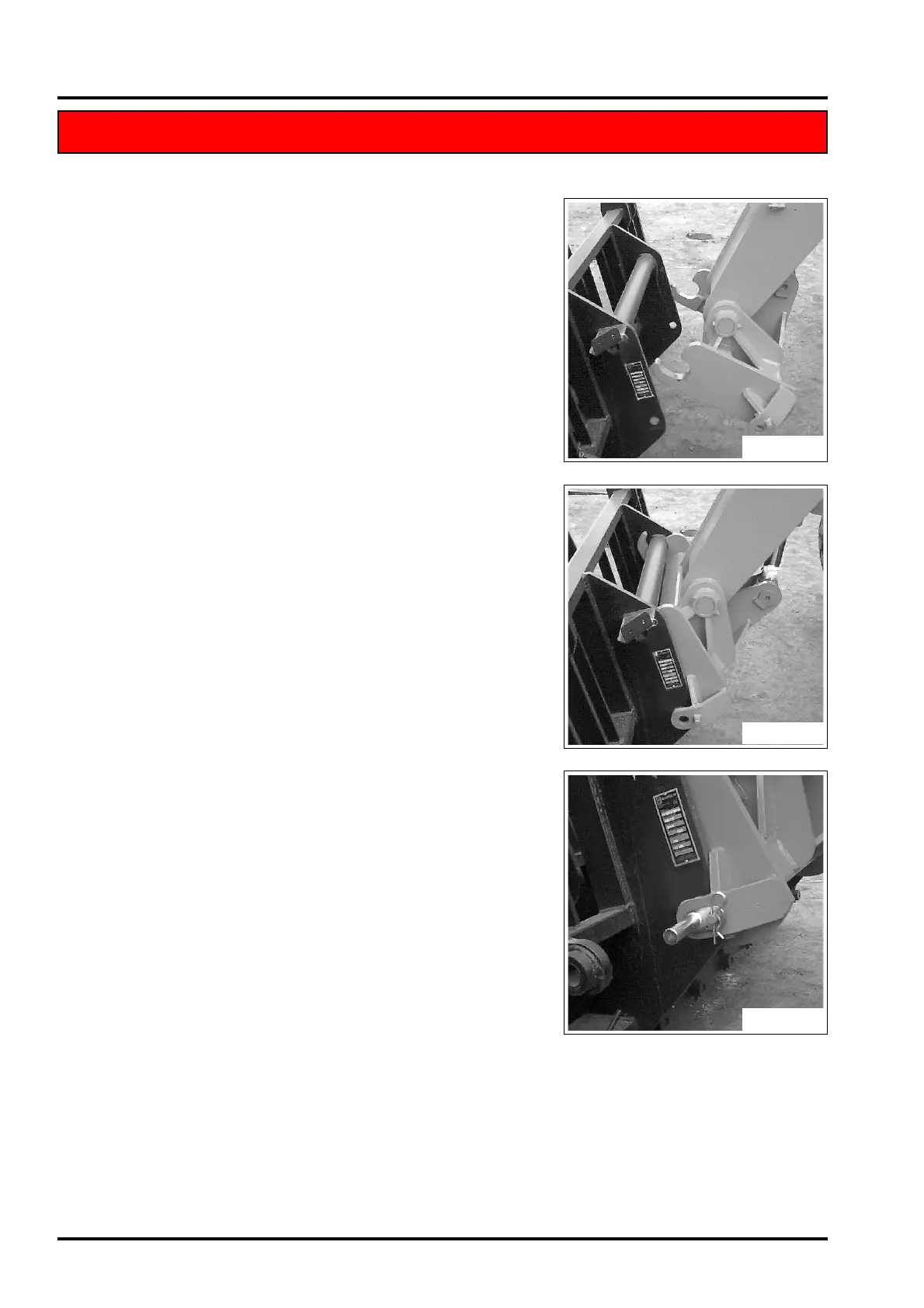
MANUAL LOCKING
- Take the locking pin on the support and fix the accessory (Fig.C). Do
not forget to fit the split-pin.
MANUAL RELEASE
- Proceed in reverse direction to the MANUAL LOCKING procedure,
taking care to replace the locking pin in the support on the frame.
REMOVING (AND PUTTING DOWN) THE ACCESSORY
- Proceed in reverse direction to the ENGAGING THE ACCESSORY
procedure, taking care to place it in a safe position on firm, flat
ground.
ACCESSORY WITHOUT HYDRAULIC SYSTEM AND MANUAL LOCKING
ACCESSORY WITHOUT HYDRAULIC SYSTEM AND MANUAL LOCKING
Fig. A
Fig. B
Fig. C
 Loading...