32
4
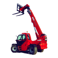
MHT 10120 L M
SS
eries
KEY TO TRANSMISSION HYDRAULIC SYSTEM DIAGRAM
COLLETTORE = Manifold
D. = Directional control valve
DF = Flow divider
F.A. = Intake filter
F.R. = Drain filter
I.D. = Power steering unit
M = Control lever
MC = Brake pump
M.I. = Hydrostatic motor
M.T. = Engine
M.V. = Fan Motor
P. = Movement pump
P.H. = Hydrostatic pump
P.H. (G) = G connection of hydrostatic pump
R. = Hydraulic fluid tank
Rd = Oil radiator
RFS = Parking brake control lever
V.I. = Inching valve
VM = Solenoid and relief valve
VSLR = Slow-fast selector valve
 Loading...

