INSTALLATION INSTRUCTIONS
Figures 1,2, &3
Insure that the proper steer tube has been delivered on your fork.
The steer tube may need to be cut to length to fit your bicycle
head tube. If you are not familiar with this procedure or do not
have the proper tools to cut the steer tube it is recommended that
you seek a dealer with a qualified bicycle mechanic to perform
installation.
! WARNING
The steer tube and stanchions (inner legs) are a one time
precision press fit at the factory and cannot be removed from
the crown. Replacement of the entire crown/steerer
assembly must be done to change steer tube lengths or
diameters. Removing and replacing the steer tube or
stanchions will result in an unsafe condition and should
never be done.
1. Remove old forks from bicycle.
2. Measure and cut the steer tube to fit your bicycle head
tube.
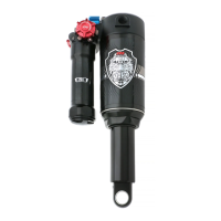
3. Remove crown race from old forks and press onto 98
XVERT Steerer until seated on crown (Figure 1).
4. Clean and grease headset bearings and races of bicycle.
5 Install lower bearings on fork crown race.
6. Insert steer tube into head tube of frame.
7. Install upper bearings, spacers, and stem.
8. Install stem cap and screw, tighten until slack just
disappears.
9. Install handlebars to desired height. Torque stem handlebar
pinch screws and stem clamping system to manufacturerÕs
instructions.
10. Install brakes and adjust per manufacturers instructions.
Note: All 98 Manitou Forks Forks are equipped with a
secondary catch dropout.
11. Adjust front wheel quick release to clear the 0.275"
(7MM) thick secondary catch dropout. The quick release
must be tightened after it is properly seated into the dropout
counter bores.
Ensure that there is adequate thread engagement (4 or more
threads with the release adjusted to lock) due to the wider
adjustment. Install front wheel to bicycle per manufacturers
specification.
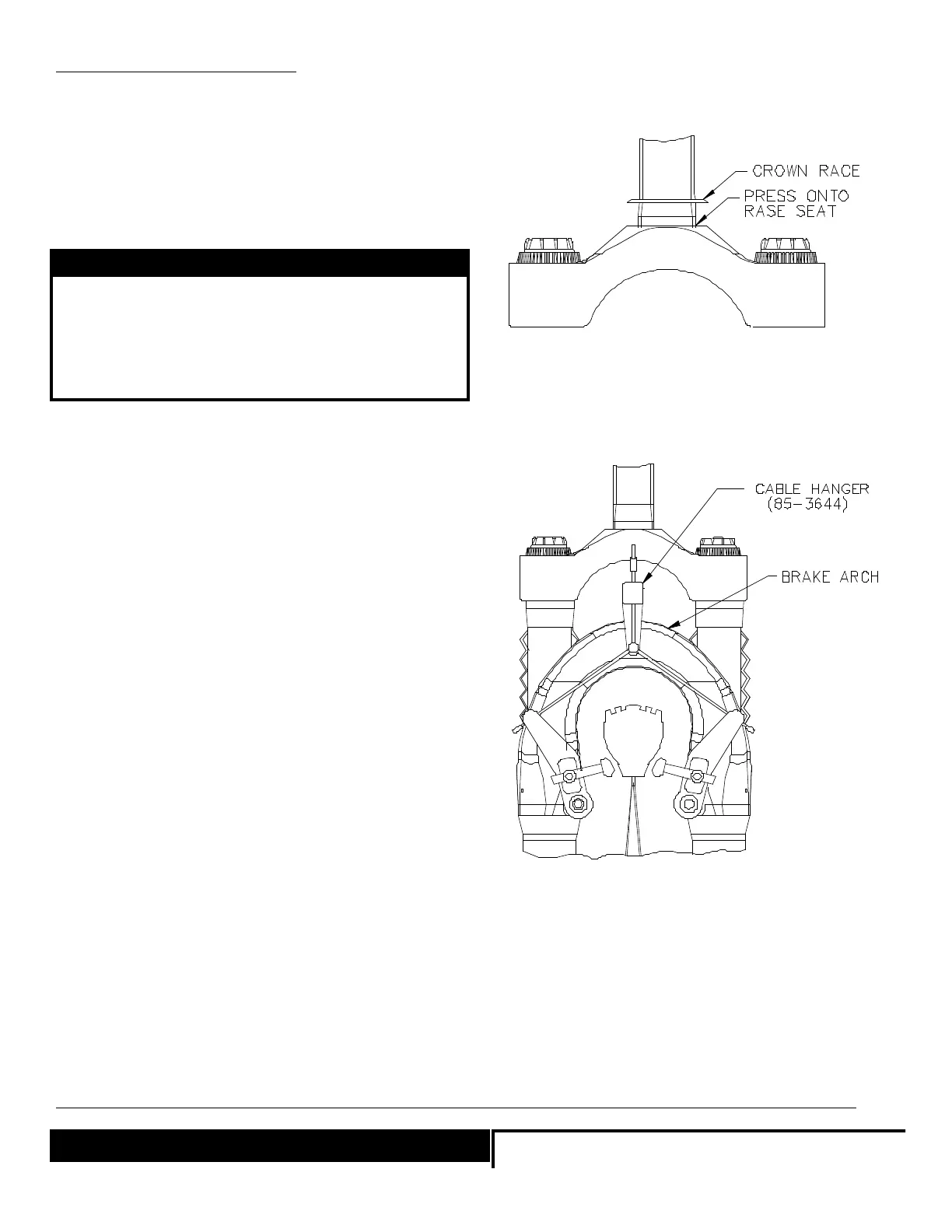
12. Install brake cable per manufacturers instructions.
Note: The XVERT comes equipped with a hangerless arch.
Brake cable hangers that attach to the arch are available
through your dealer P/N 85-3644. See Figure 2
FIGURE 1: RACE INSTALLATION
FIGURE 2: BRAKE CABLE ROUTING
Page 2
_______________________________________________________________________________________________________
! WARNING
When installing wheel or any new tire check the minimum tir
clearance. Measure from the highest point on the tire to the