OPERATING CONTROLS AND PROCEDURES 777 OPERATOR’S MANUAL
3-66 Published 10-01-12, Control # 044-05 v2
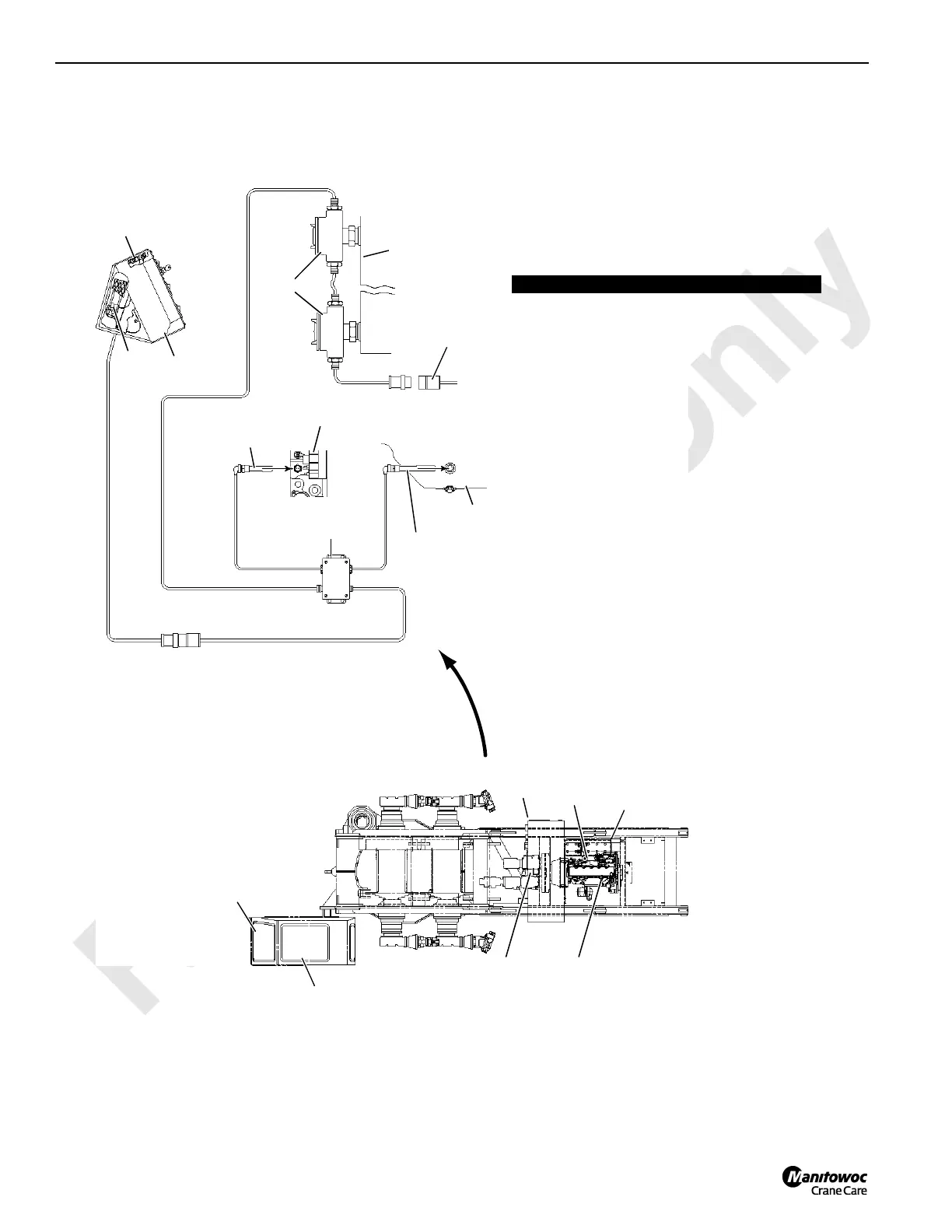
FIGURE 3-37 continu ed
Item Description
1 Power Supply Cord
2Hydraulic Tank
3 Hydraulic Tank Heaters
4 Front Control Console
5 Control Console Thermostat
6 Control Console Heater
7 Engine Block (left side)
8 Engine Coolant Heater
9 Engine Oil Pan (right side)
10 Engine Oil Pan Heater
11 Junction Box (on beam under engine)
P2092
4
5
6
11 7
8
9
10
1
2
3
Operator’s
Cab
Engine
5
4
6
1
2
3
7
8
9
10
11
240 Volt AC Option

 Loading...


