Manitowoc Published 10-01-12, Control # 044-05 v2 3-49
777 OPERATOR’S MANUAL OPERATING CONTROLS AND PROCEDURES
3
Table 3-6
Display Abbreviations
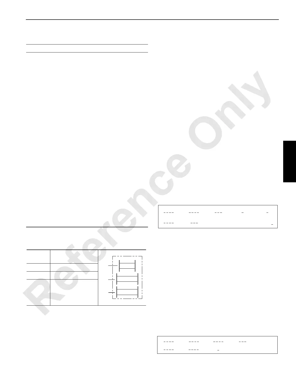
Table 3-7
Drum Identification
DIAGNOSTIC DISPLAY
To activate the diagnostic display screens, depress the limit
bypass switch and scroll up. Once this step is performed,
you can scroll up and down through the diagnostic screens in
addition to the normal operating screens. To deactivate the
diagnostic screens, depress the limit bypass switch and
scroll down. The normal operating screens will remain
active.
The diagnostic display provides information about the status
of all main crane components as well as the controller inputs
and outputs during operation. There are a total of twelve
diagnostic screens:
• Six which display information about particular crane
functions — DRUMS 1, 2, and 8, BHST (Boom Hoist),
SWING, and TRACK.
• Three which display information about digital inputs and
outputs — D1 (outputs from crane controller), D2 (inputs
to crane controller), and A1 (handle/pedal inputs to
crane controller).
• Three which display controller programming information
— A2, A3, and D3. These screens are for factory use
only, and are not shown in this section.
See Table 3-7 for drum identification, Figure 3-31 for handle
and pedal identification, and Figure 3-32 for pump
identification.
Drum 1, 2, and 8
1. Handle command in percent from neutral (+ raise, – lower)*.
2. Pump command in percent from neutral (+ raise, – lower).
3. Motor command in percent (0% max. displacement, 100%
minimum displacement).
4. Parking brake command (1 release, 0 engage).
5. Clutch command (1 release, 0 engage) (applies only to drums
with free fall, otherwise has no meaning).
6. Measured pump pressure (port A) in psi.
7. Measured drum speed in rpm (+ raise, – lower).
X = Corresponding drum number appears.
*For certain operating conditions the handle command can be set to
neutral by the controller even if the handle is not in neutral.
BHST (Boom Hoist)
Abbreviation Definition
+.........................................
–.........................................
%........................................
A1 ......................................
A2 ......................................
A3 ......................................
ANG ...................................
AUX....................................
CALIB.................................
CHRG ................................
CON...................................
D1 ......................................
D2 ......................................
D3 ......................................
DEG ...................................
DEG F ................................
FWD...................................
FFall ...................................
HYD ...................................
LUFF ..................................
MIN ....................................
MAX ...................................
PRESS...............................
PSI .....................................
PSIA...................................
RPM...................................
RIN.....................................
SEND.................................
SYS....................................
TEMP.................................
Plus
Minus
Percent
Handle Inputs
Pump Control Outputs
Programmer’s Screen
Angle
Auxiliary
Calibration
Charge
Configuration
Digital On-Off Inputs
Digital Inputs
Digital Inputs or Outputs
Degrees (angle)
Degrees Fahrenheit
Forward
Free Fall
Hydraulic
Luffing
Minimum
Maximum
Pressure
Pounds Per Square Inch
Pounds Per Square Inch
Absolute
Revolution Per Minute
Remote Input Node
Sender
System
Temperature
Drum
Number
Drum
1 Front Load Drum
2 Rear Load Drum
8 Auxiliary Load Drum
(in boom butt)
1
2
8
A817
1
6
2
7
3
DRUM
4 5
X
1
5
23
BHST
4
6
7

 Loading...


