Manitowoc Published 10-01-12, Control # 044-05 v2 3-37
777 OPERATOR’S MANUAL OPERATING CONTROLS AND PROCEDURES
3
FUSES
Fuse Location
Fuses are located in the front of the left enclosure (Figure 3-4).
Fuse Identification
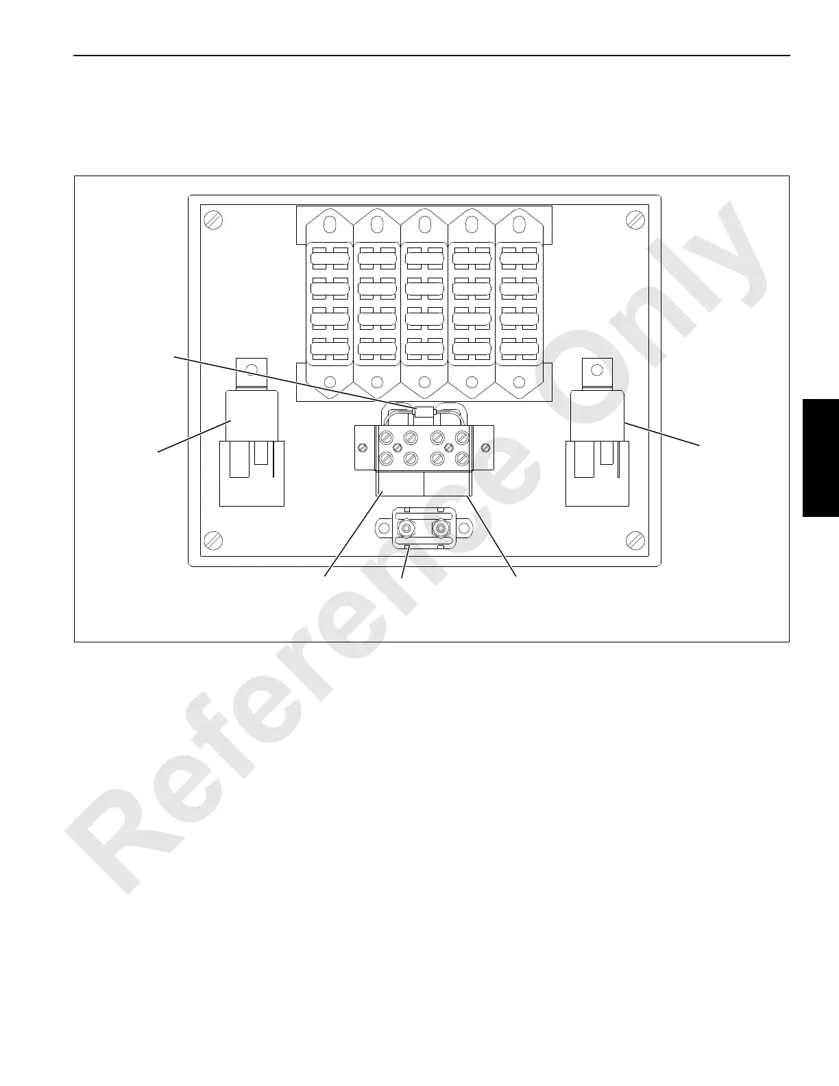
FIGURE 3-22
SYS
GND
12–15
VDC
F20
F19
F18
F17
F16
F15
F14
F13
F12
F11
F10
F9
F8
F7
F6
F5
F4
F3
F2
F1
(k2)
70 amp DC Power
Output Relay
(k1)
70 amp Cab
Power Relay
Transient
Suppressor
Diode
50 amp
Controller
Circuit Breaker
12–15 VDC
Power Supply
(for trouble
shooting only)
System
Ground
268350
Fuse
Number
Description
Fuse
Number
Description
F1 Cab Heater (8H) 15 amp F11 Spare 10 amp
F2 Front Wiper (8W1) 10 amp F12 10 VDC Reg. Supply (87FA) 3 amp
F3 Overhead Wiper (8W2) 10 amp F13 Heater Fan/Hi-Speed (5A) 20 amp
F4 Spare 20 amp F14 Lights/Accessories (5A) 20 amp
F5 Spare 15 amp F15 Horn (5H) 20 amp
F6 Swing/Pawls (8S) 15 amp F16 Engine/Dome Light (5D) 10 amp
F7 Defogger Fan (8F) 10 amp F17 20 amp
F8 Gauges/Load Cells (8A) 10 amp F18 15 amp
F9 Sensor Inputs (8D) 10 amp F19 10 amp
F10 Transducers/Encoders (8T) 10 amp F20 3 amp