SET-UP AND INSTALLATION 777 OPERATOR’S MANUAL
4-76 Published 10-01-12, Control # 044-05
CLAMSHELL REEVING
General
For clamshell operation, perform following steps:
• Remove jib or upper boom point.
• Remove block-up limit chains and weights. Connect
electric cables from limit switches to shorting plugs on
boom top junction box.
• Remove load sensing sheaves for rated capacity
indicator/limiter.
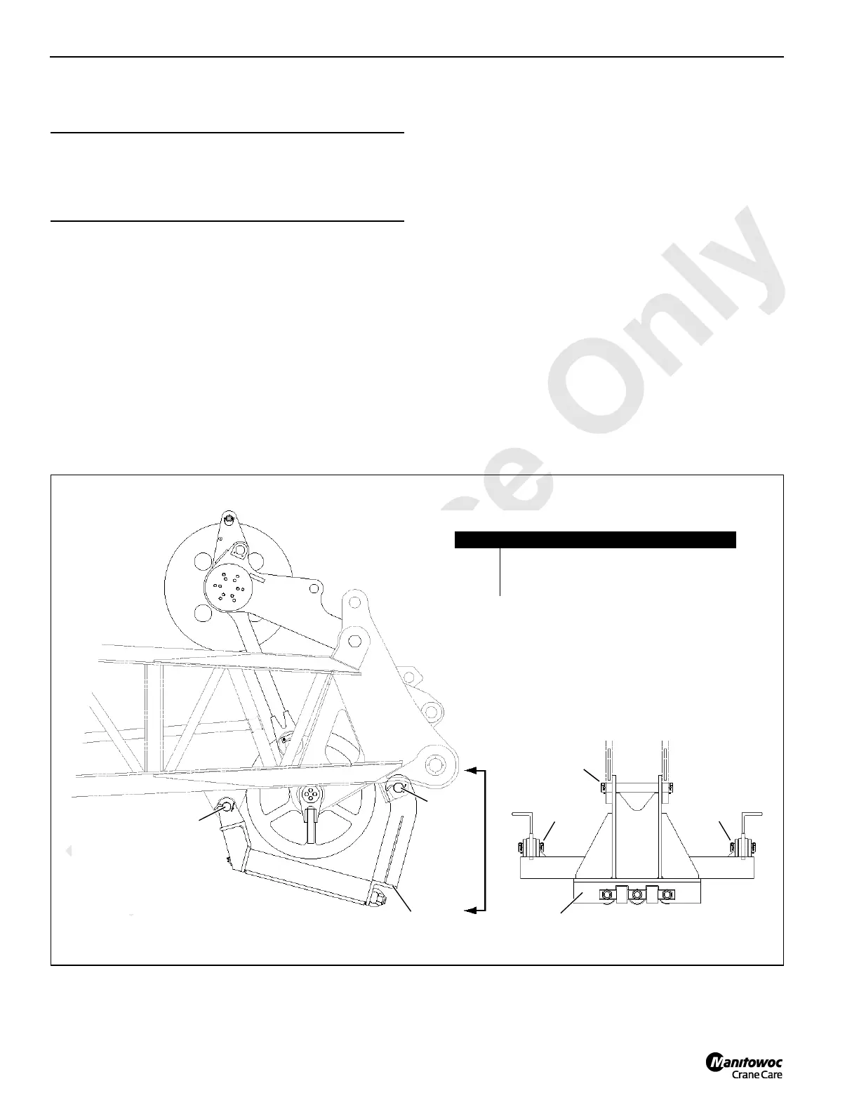
• Install boom point wire rope roller guide as shown in
Figure 4-49.
• Position boom top wire rope guide sheaves as shown in
Figure 4-50. Sheaves must be positioned at indicated
dimensions to ensure proper fleet angles.
• Route wire rope from load drums as shown in
Figure 4-50.
Wire Rope Specifications
See Wire Rope Specifications chart in Capacity Chart
Manual for following information:
• Wire rope lengths and hoisting distance notes for
various parts of line.
• Maximum spooling capacity of load drums.
Wire Rope Installation
See Wire Rope Installation and Maintenance for following
instructions:
• Anchoring wire rope to drums.
• Installing wire rope on drums.
• Anchoring wire rope to wedge sockets.
CAUTION
Wire Rope Damage!
Failing to observe following precautions can result in
damage to wire rope and wire rope guide sheaves.
Item Description
1 Wire Rope Roller Guide
2 Pin with Hitch Pins and Cotter Pins
3 Pin with Hitch Pins and Cotter Pins (2 each)
View at Lower Boom Point
3
1
2
3
2
1
178177
FIGURE 4-49
3