Grove Published 3-23-2020, Control # 654-04 5-27
GRT655/655L OPERATOR MANUAL SET-UP AND INSTALLATION
12. Slightly raise and/or lower the boom to help control the
boom extension. Using the tag line attached to the tip of
the boom extension, manually swing the boom
extension into place ahead of the boom nose, engaging
the attachment lugs with the anchor fittings on the left
side of the boom nose (Figure 5-22).
13. Attach the boom extension base section to the boom
nose by installing the left side attachment pins through
the anchor fittings and attachment lugs.
Use an impact wrench and the provided extension
(80104116) and socket (80104383) to turn the jack
screw counterclockwise to engage the attachment pins
(1, Figure 5-22). Make sure the attachment pins are fully
engaged.
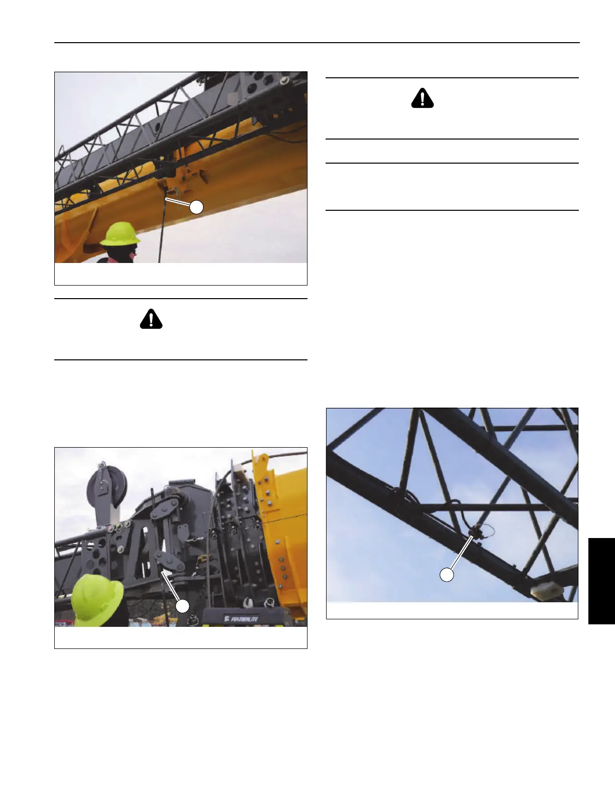
14. Connect Anti-Two-Block cables:
a. Remove the Anti-Two-Block cable end connector
(1, Figure 5-23) from the stowage clip on the boom
extension.Route the cable through the boom
extension and over to the Anti-Two-Block switch at
the boom nose.
b. Disconnect the boom anti-two-block switch cable
end connector from the anti-two-block switch at the
boom nose and connect it to the boom extension
anti-two-block cable end connector (1, Figure 5-24).
DANGER
When erecting the boom extension, make sure that all
personnel and equipment are kept clear of the swing path.
DANGER
Do not modify the attachment points to permit the
installation of the attachment pins.
CAUTION
To prevent possible damage to the sheave wheel, do not
place blocking under the boom extension sheave wheel.

 Loading...


