SET-UP AND INSTALLATION GRT8100 OPERATOR MANUAL
4-26 Published 3-25-2020, Control # 595-10
27. Using control pendant, fully retract middle stowage
bracket (10, Figure 4-20).
28. Ensure the two stowage lugs on the boom extension
base section are fully engaged with the pins (14,
Figure 4-20) on front stowage bracket (5, Figure 4-20).
NOTE: If boom extension fly section and boom extension
base section are being stowed together, perform
step 29.
If boom extension fly section remained on boom
stowage brackets, perform steps 30 through 31.
29. Secure boom extension fly section to rear stowage
bracket (1, Figure 4-20) on the boom base using the
attachment pin. Secure attachment pin with retaining
clip.
Skip to step 32.
30. Remove attachment pin from stowage holder on the
boom extension base section and use it to secure the
boom extension fly section to the boom extension base
section. Secure attachment pin with retaining clip.
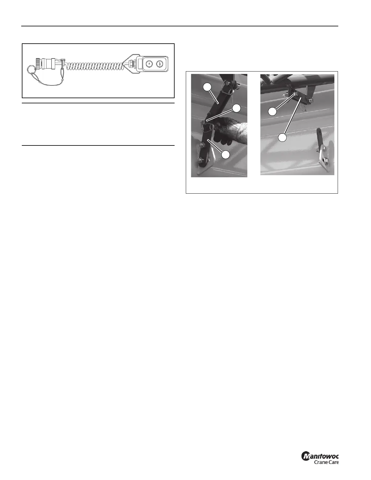
31. Remove pin (1, Figure 4-19) from boom base
attachment bar (3). Move locking bar (2, Figure 4-19;
10, Figure 4-20) to boom extension base section and
install pin (1). Secure with retaining clip.
32. Disconnect control pendant and replace caps.
33. Extend boom in AUTO mode with B mode selected, or
Manual Mode with Section 1 selected, until boom stops.
NOTE: Reaching this stopping point is required for the
Boom Extension Rigging Mode process.
34. Retract boom until it stops.
NOTE: When boom reaches this stopping point and
section 1 and section 2 proximity switches are
activated, the Boom Extension Rigging Mode is
complete and restrictions on the boom operating
modes are removed
35. Rig boom nose and hoist cable as desired. Operate
crane using normal operating procedures.
CAUTION
Failure to maintain proper clearance between the boom
extension base section anchor fittings and boom nose
attachment fittings could cause fittings to contact each
other during operation of the boom.
6642-8
FIGURE 4-19
6642-9
2
2
3
1
1

 Loading...


