Grove Published 3-25-2020, Control # 595-10 4-25
GRT8100 OPERATOR MANUAL SET-UP AND INSTALLATION
boom extension fly section to side of the boom
extension base section.
e. Connect locking bar (9, Figure 4-20; 1, Figure 4-16)
to boom extension base section attachment bar (2)
using pin (3). Secure with retaining clip.
14. Lower boom to minimum elevation and remove rope.
15. Attach rope to boom extension base section tip.
16. Raise boom to horizontal.
17. Extend boom approximately 12 in so boom extension
base section stowage lugs will line up in front of the
middle stowage bracket guide ramp (10, Figure 4-20)
and stowage pins (14, Figure 4-20) on the front stowage
bracket assembly (5, Figure 4-20) when the boom
extension is positioned to the side of the boom base.
18. Using the jack handle (4, Figure 4-17) stored on the left
side of the boom nose, extend boom extension
alignment jack (3, Figure 4-17) until the lower left
attachment pin is free from the anchor and attachment
fittings of the boom extension base section and boom
nose. Remove attachment pin and stow on boom
extension base section, then secure with retaining clip.
19. Retract alignment jack to its original position, then return
the jack handle to its stowed position.
20. Remove top left attachment pin from the anchor and
attachment fittings of the boom extension base section
and boom nose. Stow attachment pin in boom extension
base section and secure with retaining clip.
21. Slightly raise or lower boom to help control the boom
extension base section swing. Using rope attached to tip
of the boom extension base section, swing boom
extension base section to the side of the boom base.
22. Elevate boom and push in on the boom extension base
section to align the stowage lugs on the boom extension
base section with the guide ramp and stowage pins on
the stowage brackets, then fully retract the boom.
23. Fully lower boom.
24. Secure boom extension base section to front stowage
bracket (5, Figure 4-20) on boom base using lock hitch
pin (13, Figure 4-20). Ensure lock hitch pin is pushed in
all the way, then secure with retaining clip.
25. Remove upper an lower right attachment pins from the
anchor and attach fittings of the boom extension base
section and boom nose. Stow attachment pins in the
stowage lugs on the right side of the boom extension
base section, then secure with retaining clips.
26. Remove caps and connect boom extension mount
control pendant to connector on front of boom base.
DANGER
When stowing the boom extension base section, ensure
all personnel and equipment are kept clear of swing path.
Uncontrolled movement of boom extension base section
can cause death, injuries, or damage to equipment.
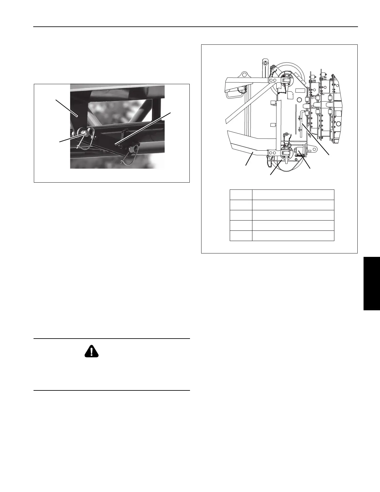
FIGURE 4-17
8177-2
1
2
3
Item Description
1 Boom Extension
2 Boom Nose
3 Alignment Jack
4 Alignment Jack Handle
4
 Loading...


