500E2 OPERATOR MANUAL OPERATING CONTROLS AND PROCEDURES
National Crane Published 07-26-2019 Control # 111-06 3-11
When trip force is reached, the jib load limiting device breaks
electrical continuity to the work port unloader solenoid in the
main control valve. When power is removed from this
solenoid, the unloader valves allow the oil flowing to hoist up,
telescope out and boom down to flow to tank. This path to
tank will prevent further operation of these functions. When
the overload condition is corrected by hoisting down,
retracting the boom, or raising the boom, the jib load limiting
device allows the work port unloader solenoid to be powered
thereby allowing the crane to function normally.
During operation at near capacity loads, care must be taken
to operate the controls smoothly or the system may be
shocked into the dump mode prematurely.
The override system consists of a key switch and a
momentary push button switch. The key switch provides
power to the momentary push button switch located on the
console. To momentarily override, activate key switch and
depress push button on console. This will activate the work
port unloader solenoid and return power to hoist up,
telescope out, and boom down functions. The override
switch is not to be used during normal use of the crane or as
an aid in using the crane in an overload or two-blocked
condition.
Do not expect the Hydraulic Capacity Alert System and the
Jib Load Limiting Device to detect all possible overload
conditions.
These systems do not prevent structural or stability
overloads to the crane or hoist caused by:
1. Freely swinging loads or operating in an out-of-level
condition which will result in excessive side loading.
2. Side loading due to pulling sideways on the boom with
boom rotation or load hoist. Load must always be
directly under boom tip.
3. Sudden load movements from erratic operation of the
crane functions which will result in excessive shock
loading.
4. Improper loadline reeving for loads larger than single
line pull capacity.
5. Extending the boom without first paying out the loadline
which can result in deadheading (two blocking) the
loadline against the boom tip.
6. Loads with lift cylinder fully retracted.
7. Excessive induced loading during auger system
operation.
8. Operation without outriggers and stabilizers fully
deployed or inadequate footing for the outriggers and
stabilizers.
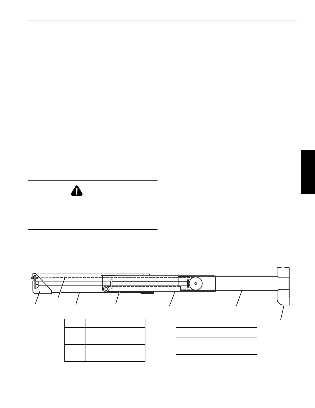
THREE SECTION BOOM OPERATION
A rod-fed, double-acting cylinder, attached to the 1
st
and 2
nd
boom sections, supports and propels the 2
nd
boom section.
The extend cables attach to the base end of the 1
st
boom
section, are reeved around sheaves attached to the cylinder,
and attach to the base end of the 3
rd
boom section providing
support and extension of the 3
rd
boom section.
CAUTION
The HCA and the Jib Load Limiting Device are intended to
be used as only aids to prevent overload conditions. Do
not use the Hydraulic Capacity Alert System and the Jib
Load Limiting Device as substitutes for safe operating
practices as out lined in this manual.
Item Component
1. Base
2 Extend Cable
3Tip
4
3
rd
Section
THREE SECTION BOOM
5
2
nd
Section
6 Retract Cable
7
1
st
Section
Item Component
1
6
5
7
4
2
3

 Loading...


