SET-UP OPERATOR MANUAL 500E2
4-12 Published 07-26-2019 Control # 111-06
Jib Jack Procedures
The Jib Pin alignment device (Jib Jack) is an aid for installing
the fourth or “last” jib pin when setting up a jib. This device
has been designed to line up the bottom jib pin hole on the
left side of the crane the hole in the boom ear.
The jib pin alignment device consists of a hydraulic jack
mounted horizontally on the underside of the jib. A handle for
the jack is provided and is installed above the jack on the
side of the jib.
Prior to using the Jib Jack, complete Steps 1 to 12 in the
“Side Folding-Swing Around Deployment Procedure”.
1. Remove jack handle and using the flattened end, close
jack release valve by turning the handle clockwise until it
is firmly closed.
2. Insert the round end of the handle into the handle sleeve
and pump jack until ram contacts boom sheave case.
3. Continue to pump slowly until jib pin holes exactly
aligned with hole in boom ear. At this time the final jib pin
can be easily tapped into position.
If hole alignment is “over shot” due to jacking too far, the
jack can simply be relieved and the process repeated.
To relieve the jack, use the flattened end of jack handle
to slowly turn relief valve counter clockwise no more
than one full turn.
4. After all jib pins are installed, relieve jack.
The jib pin alignment device is also useful when removing
the “fourth” pin. Use the jib jack to relieve jib weight induced
pressure on the “fourth” pin and it will be much easier to
remove.
Once the jib has been erected or stowed, it is important that
the jack handle be properly placed back on its stowage
hooks and that the cotter key be properly placed in the
stowage hook to retain the handle on the hook.
When Jib is stowed on side of crane, always leave ram and
handle sleeve pushed all the way down to reduce exposure
to rusting.
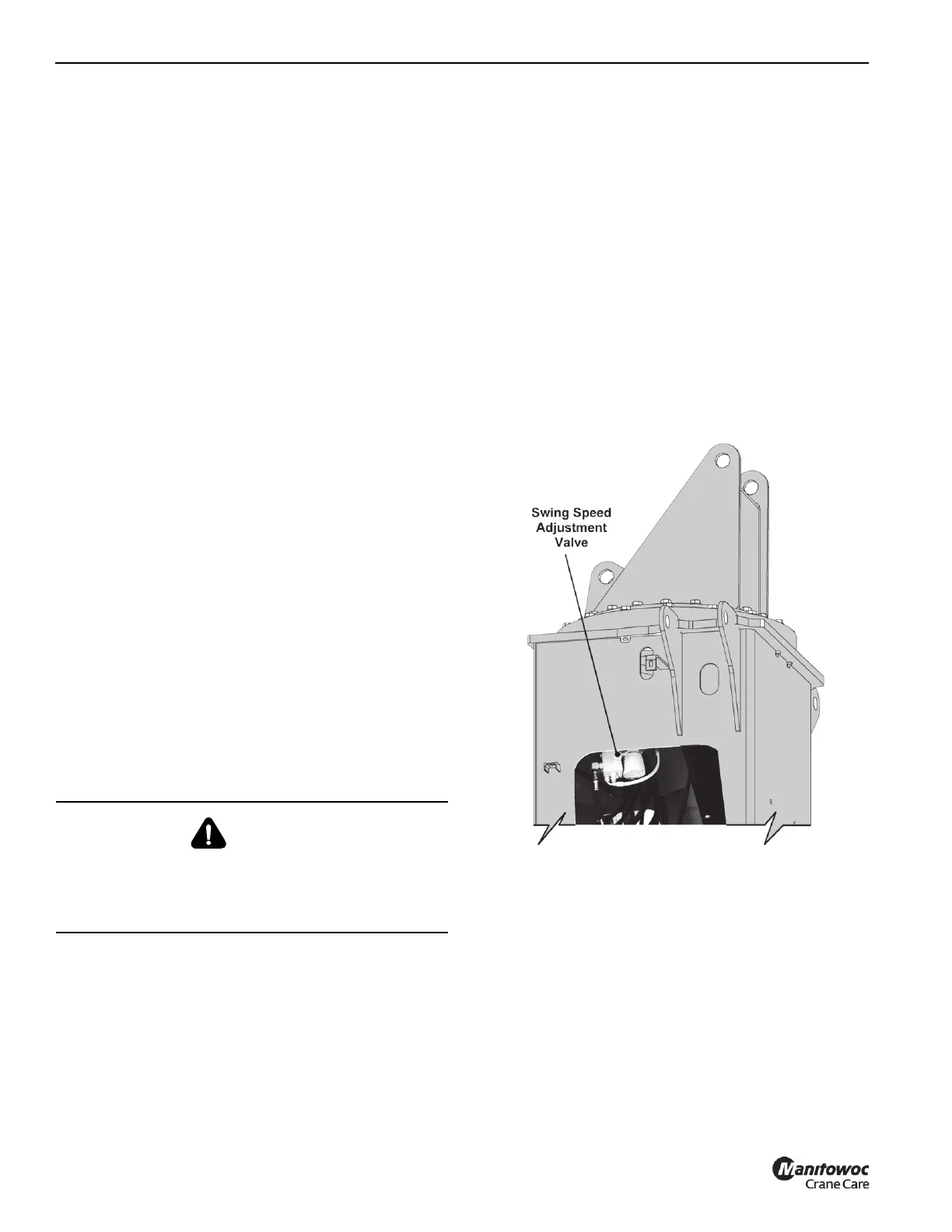
ADJUSTABLE SWING SPEED VALVE
This crane is equipped with an adjustable swing speed
valve. This valve allows the operator to limit the maximum
swing speed of the machine to suit operator preference or
varying applications.
An adjustment dials located on the swing holding valve
mounted on the swing motor inside the crane frame. The
valve has an adjustment screw with a lock collar. Loosen the
lock collar when adjusting the speed, then tighten the lock
collar to maintain swing speed limit setting. The adjustment
dial allows the maximum swing speed to be reduced as
required.
CAUTION
Avoid “shock loads” created by quickly opening and
closing the release while jack is under load. This may
result in overloading of the hydraulic circuit and possible
damage to the jack.

 Loading...


