2-2
Installation Instructions Section 2
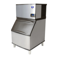
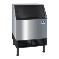
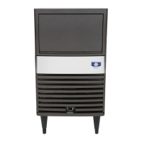
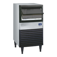
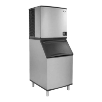
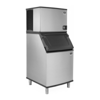
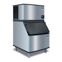
Location of Ice Machine
The location selected for the ice machine must meet
the following criteria. If any of these criteria are not
met, select another location.
• The location must be free of airborne and other
contaminants.
• The air temperature must be at least 35°F (1.6°C),
but must not exceed 110°F (43.4°C).
• The location must not be near heat-generating
equipment or in direct sunlight.
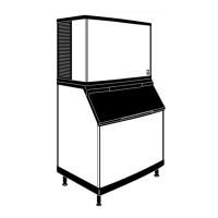
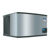
Ice Machine
Head Section
Top/Sides 5” (127 mm)*
Back 5” (127 mm)*
There is no minimum clearance required. This value is
recommended for servicing only.
CAUTION
The ice machine must be protected if it will be
subjected to temperatures below 32°F (0°C).
Failures caused by exposure to freezing
temperatures are not covered by the warranty. See
“Removal from Service/Winterization” on page 4-
10.
Location of Condensing Unit
The location selected for the condensing unit must
meet the following criteria. If any of these criteria are
not met, select another location.
• The location must allow connection of all pre-
charged line sets, with out exceeding total
distance, rise or drop guidelines. (see page 2-7)
• Refer to the manual supplied with the condensing
unit, for Copeland’s clearance requirements.
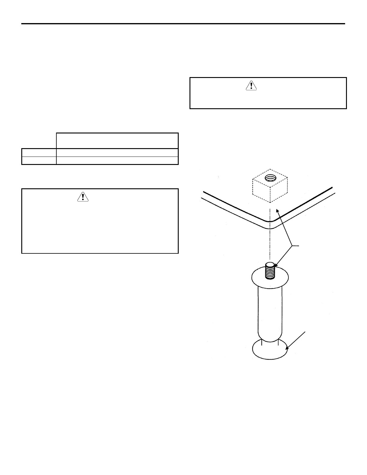
Leveling the Ice Machine
1. Screw the leveling legs onto the bottom of the
bin.
2. Screw the foot of each leg in as far as possible.
CAUTION
The legs must be screwed in tightly to prevent them
from bending.
3. Move the bin into its final position.
4. Level the bin to assure that the bin door closes
and seals properly. Use a level on top of the bin.
Turn each foot as necessary to level the bin.
Leveling Leg and Foot
SV1606
THREAD
LEVELING LEG
INTO BASE OF
CABINET
THREAD “FOOT”
IN AS FAR AS
POSSIBLE
 Loading...