6-19
Section 6 Service
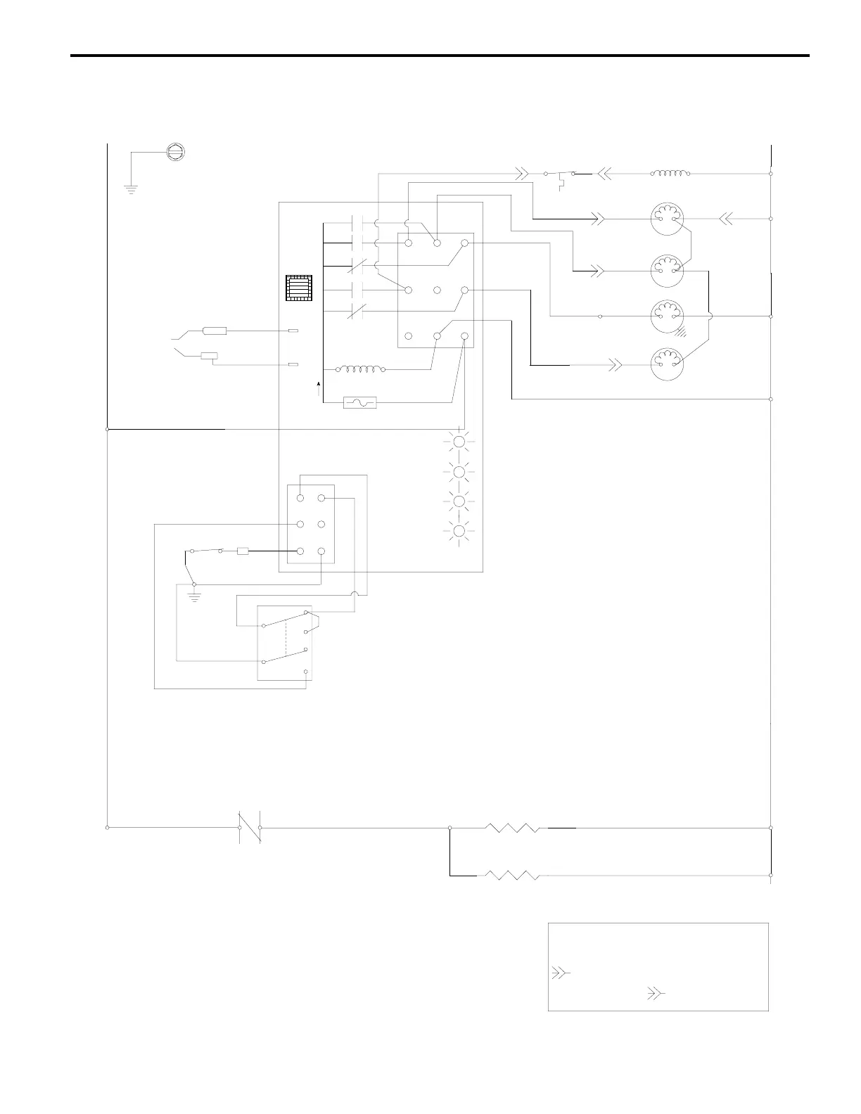
Wiring Diagram P520/P530 Ice Machines
(64) BIN
TOGGLE SWITCH
TB35
CONTACTOR
CONTACTS
(42)
(66)
(67)
SWITCH
elept
6/20/97LM
rev. 9/19/97
(33)
ICE
OFF
CLEAN
(68)
(62)
(69)
(65)
(31)
ICE THICKNESS
PROBE
WATER LEVEL
PROBE
(62)
(63)
TB35
(55)
L1
AUCS
3
TRANSFORMER
PLUG
LOW D.C. VOLTAGE
1F
1C
7A
FUSE
5
GREEN
GREEN
RED
YELLOW
2
Point of Use
Caution: Disconnect power before working
on electrical circuitry.
Drawing shown during freeze cycle
4
1
BACK OF
MACHINE
(# IS MARKED AT EACH END OF WIRE)
- BULKHEAD MULTIPIN CONNECTOR
TB - TERMINAL BOARD CONNECTION
( ) - WIRE NUMBER DESIGNATION
(34)
LOWER HEATER
ELECTRICAL
BOX SIDE
(32)
UPPER HEATER
TB30
TB30
See serial plate for voltage
WATER LEVEL SWITCH
HARVEST /
SAFTY CODE
CURTAIN SWITCH
CLEAN MODE
(58)
(56)
(57)
(73)
TB31
(98)
WATER PUMP
SUCTION
SOLENOID
(30)
(60)
AUTO RESET
125F C.O.
110F C.I.
(37)
(36)
(61)
CONTACTOR
COIL
DUMP
SOLENOID
(76)
(77)
WATER FILL
SOLENOID
(35)
(80)
TB30
TB30
(99)
TB30
(79)
(74)
(75)
(75)
TB30
L2 (N)
 Loading...