Do you have a question about the Manitowoc NEO and is the answer not in the manual?
Explains the meaning of Warning and Caution boxes used in the manual.
Describes the purpose of 'Important' and 'Note' text for procedural information.
Provides essential safety warnings including caution, warranty, and lifting advice.
Covers high voltage, refrigerant hazards, circuit protection, and safe equipment operation.
Details safety regarding vents, flammable vapors, water jets, PPE, and moving the unit.
Outlines general safety rules for using electric appliances, including cord safety.
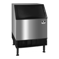
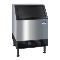
Lists the various ice machine models covered by this manual.
Breaks down the components of an ice machine model number for interpretation.
Stresses the need to complete and mail the warranty registration card promptly.
Outlines warranty coverage for parts and labor under commercial use.
Lists items not covered by warranty and requirements for authorized service.
Details what the residential limited warranty covers, its duration, and consumer rights.
Specifies exclusions from the limited warranty, including maintenance and misuse.
Provides contact details and website for obtaining warranty service and information.
Specifies the criteria for selecting an appropriate location for the ice machine.
Recommended clearances for different sides of the ice machine for efficient operation.
Instructions on how to install and adjust the leveling legs for proper machine placement.
Covers voltage variation, fuse/breaker needs, and total circuit ampacity.
Table detailing electrical specs like voltage, fuse, and amps for air-cooled models.
Table detailing electrical specs like voltage, fuse, and amps for water-cooled models.
Advice on water treatment and connecting to a potable water source.
Rules for installing drain lines to prevent backflow and ensure proper drainage.
General procedure for cleaning and sanitizing the ice machine interior.
Steps for initiating, pausing, and stopping the cleaning cycle via the touch pad.
Details cleaner amounts required for different models during the cleaning cycle.
Instructions for mixing cleaning solution and cleaning internal components.
Instructions for mixing sanitizer solution and sanitizing internal surfaces.
Steps for removing float switches, including safety precautions.
Instructions for removing the water trough by unscrewing.
Steps for removing the ice damper and bin switch cover.
Instructions on how to loosen and remove the water distribution tube.
Procedure for performing preventative maintenance cleaning, including cleaner amounts.
Key inspection points like leaks, tubing, and airflow requirements.
Explains why condenser cleaning is vital and outlines safety measures.
Detailed steps for preparing the ice machine for removal or winter storage.
Important note regarding the bin seal during reinstallation.
Describes the functions of each touch pad button and indicator lights.
Details how to start, pause, abort, and stop the cleaning cycle.
Explains the function of the bin full and service indicator lights.
Describes the water purge, freeze, harvest, and full bin cycles.
Explains freeze time lock-in, maximum cycle times, and water fill valve operation.
Details conditions for Safety Limits 1 and 2 based on cycle times.
Details conditions for Safety Limit 3 related to freeze time and water sensing.
Table showing energized components during the ice making sequence.
How to check and adjust ice cube thickness settings.
Procedure for using the control board test mode for diagnostics.
How to operate the machine for diagnostics when the bin and touch pad are removed.
Step-by-step guide to diagnose why the ice machine is not running.
Diagnosing issues when the machine fails to enter the harvest cycle due to float switch problems.
Diagnosing issues when the machine enters harvest cycle before ice is released.
Method for checking actual ice production against published data.
Checklist for critical installation and visual inspection points.
Checklist for diagnosing water-related problems affecting ice production.
Describes typical ice formation patterns on the evaporator surface.
Details abnormal patterns and their potential causes.
Details conditions for Safety Limits 1 and 2 based on cycle times.
How to identify which safety limit has been activated using control board lights.
Lists potential causes for Safety Limit 1, covering installation, water, electrical, and refrigeration systems.
Lists potential causes for Safety Limit 2, covering installation, water, electrical, and refrigeration systems.
Lists potential causes for Safety Limit 3, focusing on water system and electrical issues.
Procedure for measuring and comparing discharge pressure to normal operating ranges.
Lists potential causes for high discharge pressure, including installation and refrigerant issues.
Guide for analyzing suction pressure, emphasizing comparison with discharge pressure.
Details how to compare actual suction pressure readings with published data.
Lists potential causes for high suction pressure, including installation, discharge pressure, and refrigerant issues.
Lists potential causes for low suction pressure, including installation, discharge pressure, and refrigerant issues.
Explains the role and operation of the harvest valve during freeze and harvest cycles.
Describes symptoms of harvest valve failing to open or remaining open.
Procedure for testing harvest valve operation using temperature comparison.
How to measure and analyze evaporator inlet/outlet temperature differences for diagnostics.
Procedure for measuring compressor discharge line temperature and its significance.
Explains the meaning of high and low discharge line temperatures at the end of the freeze cycle.
Introduction to diagnostic tables, emphasizing prior correction of electrical/water issues.
Instructions for completing the operational analysis column with check marks.
How to sum check marks and proceed to the final analysis.
Diagnosis and solution for a leaking harvest valve.
Diagnosis and solution for low charge or TXV starving issues.
Diagnosis and solution for TXV flooding issues.
Diagnosis and solution for compressor problems, including warranty credit procedures.
Chart correlating ice production and formation patterns with diagnostic columns.
Chart correlating pressure readings with diagnostic columns.
Procedure for checking the main fuse using an ohmmeter and safety precautions.
Explains the functions of the bin switch and its control over ice making.
Procedure for testing the bin switch continuity using an ohmmeter.
Steps to verify normal operation of the touch pad buttons.
Procedure for testing touch pad circuits using an ohmmeter and connector pinout.
Explains the purpose and operation of the harvest and ice thickness float switches.
Steps for checking float switch operation and making adjustments.
Procedure for checking compressor winding resistance and overload status.
Diagnosing causes of compressor locked rotor or high amperage draw.
Explains the fan cycle control's role in regulating discharge pressure and its specifications.
Describes the HPCO control's function to stop the machine on high pressure and its specifications.
Explains the function and importance of the liquid line filter drier, including replacement requirements.
Defines terms like Recover, Recycle, Reclaim, and New Product Specifications for refrigerants.
Outlines Manitowoc's policy on using new, reclaimed, and recovered refrigerants.
Emphasizes avoiding contamination and replacing the liquid line drier.
Detailed steps for recovering, evacuating, and charging refrigerant.
Methods for identifying and assessing refrigerant system contamination.
Chart mapping symptoms to required cleanup procedures.
Detailed procedure for cleaning systems with mild contamination.
Detailed procedure for cleaning systems with severe contamination.
Steps for replacing controls using a pinch-off tool while retaining refrigerant.
Table listing refrigerant charge amounts for different ice machine models.
Introduction to charts used for verifying ice machine operation and performance.
Data on cycle times and pressures for U0140 air-cooled models.
Data on cycle times and pressures for U0140 water-cooled models.
Data on cycle times and pressures for U0190 air-cooled models.
Data on cycle times and pressures for U0240 air-cooled models.
Data on cycle times and pressures for U0240 water-cooled models.
Data on cycle times and pressures for U0310 air-cooled models.
Data on cycle times and pressures for U0310 water-cooled models.
Introduction to the electrical wiring diagrams included in the manual.
Explains the symbols used in the wiring diagrams.
Provides the main electrical wiring diagram applicable to all models.
Diagram showing the layout and connectors of the electronic control board.
Diagram illustrating the tubing layout for the U0140 model.
Diagram illustrating the tubing layout for U0190, U0240, and U0310 models.