10
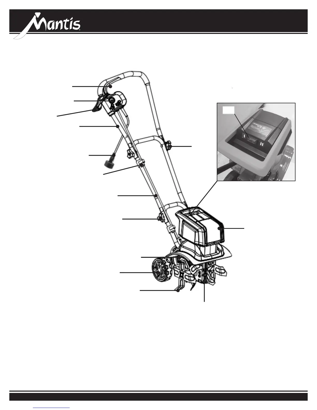
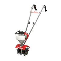
Your product
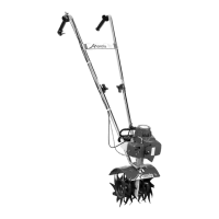
Your product
1. On/off switch 10. Guard
2. Lock-off button 11. Wheels
3. Cord retainer 12. Steel blades
4. Upper handle 13. Gear box
5. Power cord with plug 14. Motor housing
6. Cord clip 15. Air outlet
7. Middle handle
8. Upper handle knob and bolt (2)
9. Middle handle knob and bolt (2)
1. On/off switch
2. Lock-off button
3. Cord retainer
4. Upper handle
5. Power cord with plug
6. Cord clip
7. Middle handle
8. Upper handle knob and bolt (2)
9. Middle handle knob and bolt (2)
10. Guard
12. Steel Tines (blades)
13. Gear box
14. Motor housing
15. Two speed switch