19
18
8-15. CONTROL PANEL
Fig. 36
On the control panel (See Fig. 36) you will find circular LED
display with 8 numbered icons which shows useful status
information regarding the operator and its function and 3
buttons labeled “+”, “-” and “P” which allows you to set all
the adjustments of your operator.
P
1
2
1
5
3
7
2
4
6
8
In order to guarantee a trouble-free programming:
• The door must be in the “CLOSED” position and engaged
to the drive system (rail) before programming the
operator or a system reset is performed.
For proper initial operation of the operator, three basic
functions must be set using express programming:
Open Door Position
Close Door Position
Transmitter Coding
Press and hold the “P” button for approximately 2 seconds.
When LED’s 8, 1 and 2 illuminate, release the button. You
are now ready to set or change the desired adjustment. If
no buttons are pressed within 120 seconds while in
programming mode, the control unit reverts back to
operating mode.
TO MAKE OR CHANGE ANY ADJUSTMENT:
HANDY NOTE: If no changes are needed at any particular stage,
you can keep the current information and “skip” over a specific
adjustment by pressing the “P” button once. This is useful to
know if you want to change only one setting, without changing
any of the other adjustments. Simply enter the adjustment mode
by pressing and holding the “P” button for approximately 2
seconds, then press and release “P” repeatedly until your
particular adjustment is reached. This bypasses the unneeded
adjustments, and takes you right to the adjustment you want.
When your adjustment or setting is complete, simply press ”P” as
many times as needed to bypass the remaining steps and exit out
of the program, returning the operator to normal mode.
Your new operator has automatic force learning and maximum
force setting. It may be required to change force settings. If the
force needs to be increased or decreased, it should be changed
by one (1) increment at a time. The force should be set as low as
possible, just enough to allow your unobstructed door to travel
freely without reversing or stopping.
NOTE: You may exit the System Set Up at any time by pressing
the button “P” for more then 5 sec. The set up programming
can be terminated at any time and from any stage. To do so,
press the “P” button for longer than 5 seconds. When
programming is terminated, all LED’s light up once and then
turn off, one after the other.
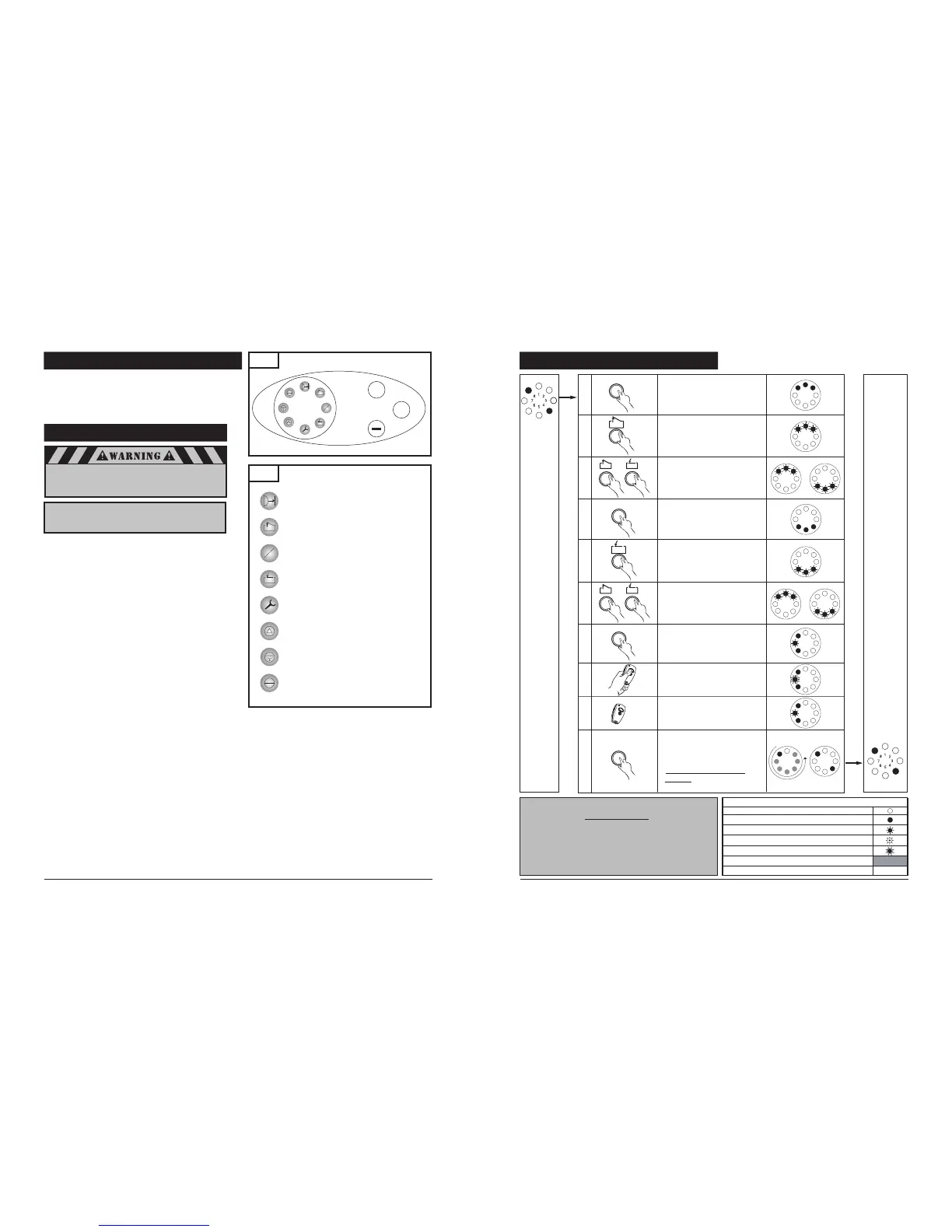
8-16. INITIAL SYSTEM SET UP
Fig. 37
1
2
Icons Description and LED’s Assignment
LED #1 Photo Eye Sensors
Connectivity/Alignment Indicator
LED #2 “OPEN Door Position”
LED #3 “Intermediate, OPEN Door Position”
LED #4 “CLOSED Door Position”
LED #5 “Reference Point”
LED #6 -----
LED #7 “Impulse (Remote Control)”
LED #8 “Power”
8-16. INITIAL SYSTEM SET UP (cont’d)
1
5
3
7
2
4
6
8
1
5
3
7
2
4
6
8
1
5
3
7
2
4
6
8
1
5
3
7
2
4
6
8
P
P
1
5
3
7
2
4
6
8
1
5
3
7
2
4
6
8
+
-
+
+
-
1
5
3
7
2
4
6
8
1
5
3
7
2
4
6
8
Legend:
LED
off
LED on
LED flashes slowly
LED pulses
LED flashes quickly
Factory default setting
Not possible
–
Power on
+
-
1x >2s< 10s
1
5
3
7
2
4
6
8
1x <1s
1
5
3
7
2
4
6
8
1
5
3
7
2
4
6
8
1
5
3
7
2
4
6
8
P
1x <1s
P
1x <1s
1
2
3
4
5
6
7
8
9
10
1
5
3
7
2
4
6
8
2
4
7
Operating
mode
Start initial system setup by
programming the door OPEN
position.
Bring the door to the desired
OPEN postion
Fine adjustment if necessary.
Adjust the OPEN door position
using (+) and (-)
Save the OPEN door position.
Start programming the
CLOSED door position.
Bring the door to the desired
CLOSED position
Fine adjustment if necessary.
Adjust the CLOSED door
position using (+) and (-)
Save the CLOSED door
position. Program the
transmitter code to GDO
Press the transmitter
button. LED #7 flashes rapidly
Release the transmitter button
Save the transmitter code
settings. End the system setup
(programming) procedure
IMPORTANT: SEE NOTE
BELOW
IMPORTANT: Align the photo eye sensors before
starting the initial system set up as
outlined in section 8-19, page 24.
IMPORTANT:
Upon completion of the initial set up, the operator
must be cycled for two complete cycles (complete
cycle comprises of one uninterrupted up activation
of the system and one uninterrupted down
activation of the system).
 Loading...