Fig. 34
Grounded Outlet
Power Cord
20
To prevent electrocution or fire, installation and wiring
must be done in accordance with local electrical and
building codes. DO NOT use an extension cord. DO NOT
use a 3 to 2 plug adapter. DO NOT modify or cut off the
grounding pin on the plug.
8-14. CONNECT TO POWER
To reduce the risk of electric shock, your opener is provided with
an insulated power cord with a 3-prong grounding plug. The cord
must be connected to a standard grounding outlet. If there is no
outlet available at the location, you must have a qualified
electrician install an approved grounded outlet in this area.
Remove operator housing by removing the four screws, two
screws located at the front by the control panel area, and two
screws located on the back of the unit, then pulling the
housing away from the chassis.
Cut the power cord close to strain relief cover, so that after cut,
there is at least 6" of wiring remaining. Remove approx. 1 ½”
of black insulation left on the cable to expose the three
conductor leads (white-neutral, black-hot, and green-ground).
Remove screw and unsnap the power cord strain relief
cover by disengaging the tabs, and remove this part (save for
reattachment later).
Remove the cut power cord and discard. Replace the strain
relief cover by snapping tabs back into place.
Using a hammer and screwdriver or punch, knock out conduit
hole, and bring in the permanent wiring and conduit.
Secure conduit to chassis (method varies depending on type
of conduit used).
Attach the incoming power leads (hot, neutral, and ground) to the
remaining internal wires using suitable wire nuts (not provided).
Tight wire leads together with a nylon cable tie to avoid the leads
from coming in contact with the relay circuit board, see Fig. 35A.
Reinstall operator housing and secure housing with screws.
Make sure that when reinstalling operator housing, no wires
will be pinched between the housing and the chassis.
Complete the remaining installation.
Turn on power at breaker.
Plug the operator into a properly grounded outlet (Fig. 34).
An indicator lights (LED’s #4 and #8) on the operator control
panel will turn on showing that the power is “On” and the
opener is ready to set the adjustments.
DO NOT operate or run the opener at this time.
PERMANENT WIRING CONNECTION:
(If required by your local electrical code)
If local codes require your operator to be connected via
permanent wiring instead of a cord and plug, your operator must
be converted, as shown in Fig. 35. Contact a qualified electrician
to run the necessary wiring to your operator and to perform the
electrical connections.
To prevent electrocution, disconnect the operator from
power and turn off power at circuit breaker for the
circuit you will be using to connect to the opener.
17
Wires: (remaining 6”)
Ground (Green)
Neutral (White)
Hot (Black)
Fig. 35
Strain relief
Fig. 35A
Nylon cable tie
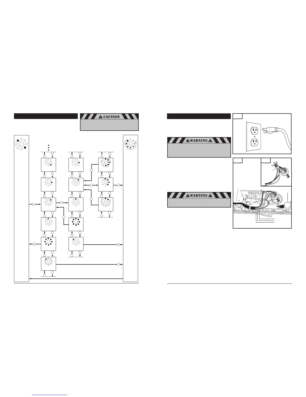
8-17. ADVANCED SETTINGS
Advanced settings p
rogramming flow chart
(Diagram illustrates: Level 2, Menu 2)
End
programming
ParameterMenu
Operating
mode
Levels
 Loading...