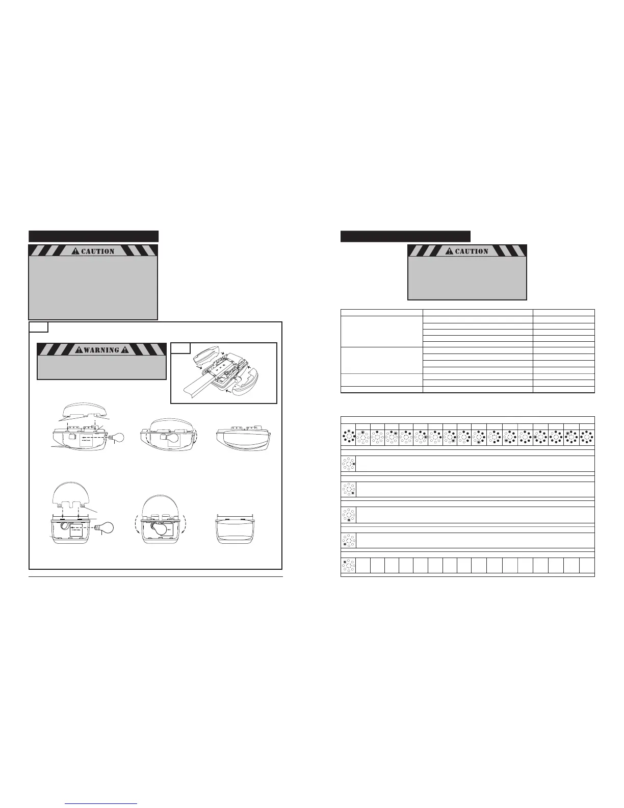
8-13. INSTALL LIGHT BULBS AND LENSES
16
Fig. 33
M4700e
M4500e
21
Lens Tabs (housing)
Chassis Slots
Housing Slots
Install Bulb
Snap lamp lens tabs
into slots in chassis
Hinge lamp lens downward
line up tabs with slots in
housing, and snap into place.
Install a maximum 60W standard neck A19 size
incandescent bulb (not provided) into lamp socket(s).
Install lamp lens(es). Two lenses for a M4700e model, see
Fig. 33A. Lenses are not interchangeable, the design is
left / right orientation dependent. One lens for a
M4500e model.
Line up lamp lens tabs with slots in housing and snap
securely into place. Repeat same procedure with second
lamp lens on the opposite side, if you have an M4700e
operator.
Line up lamp lens tabs with corresponding slots in chassis.
Snap lens onto chassis for M4500e model.
To remove lamp lens, pull lamp lens to unsnap from
housing and chassis.
NOTE: Use only A19 size standard neck incandescent light bulbs.
The use of short neck or specialty light bulbs may overheat the
endpanel or light socket.
Fig. 33A
To prevent possible serious injury and damage to the
operator when replacing the light bulbs:
• Disconnect ALL electric and battery power BEFORE
performing ANY service or maintenance.
Left lens
#80349
Right lens
#80348
A19 size standard neck
incandescent light bulb
60W (Max)
8-17. ADVANCED SETTINGS (cont’d)
Level Menu Factory default setting
Level
1 – Basic function
system reset
Menu
3: Intermediate position OPEN
–
Level
2 – Opener settings
Menu
1: “OPEN” position – operating (System) force
Setting
8
Menu
2: “CLOSE” position – operating (System) force Setting 8
Menu
3: “OPEN” position – operating sensitivity Setting 15
Menu
4: “CLOSE” position – operating sensitivity Setting 15
General overview of the programmable functions
Level 5
Menu
4: Light timer Setting 16
Menu 4: Not available
Menu 5: Soft run position OPEN
–
Menu 6: Soft run position CLOSE
–
Menu 8: RESET
–
Level 1: Functions overview
1 2 3 4 5 6 7 8 9 10 11 12 13 14 15 16
Menu 8: RESET
No Yes – – – – – – – – – – – – – –
Level 1
NOTE: Menus 1, 2 and 7 are disabled. Press “+” or “-” button to scroll or
navigate through menus.
Menu 3: Intermediate position OPEN
Set using the (+ / OPEN) and (- / CLOSE) buttons
Menu 4: Intermediate position CLOSE
not available
Menu 5: Soft run position OPEN
Set using the (+ / OPEN) and (- / CLOSE) buttons
Menu 6: Soft run position CLOSE
Set using the (+ / OPEN) and (- / CLOSE) buttons
After a system reset, all parameters are restored to the
factory settings.
• All the required function in the initial set up and advanced
settings must be re-programmed if it is required.
• The operator must be activated for two (2) complete
uninterrupted cycles in order for all restored or
operating parameters settings to be learned by the
operator again.
Level 4 – Transmitter code
programming
Menu 1: Not available
Menu 2: Intermediate position
–
–
–
Hinge lamp lens downward
line up tabs with slots in
housing, and snap into place.
Snap lamp lens tabs
into slots in chassis
Install Bulb
Housing Slots
Chassis Slots
Lens Tabs (housing)
A19 size standard neck
incandescent light bulb
60W (max)
Lens Tabs (chassis)
To prevent possible OVERHEATING of the end panel or
light socket:
• Use ONLY A19 size standard neck incandescent
light bulb(s).
• DO NOT use short neck or specialty light bulbs.
• DO NOT use halogen light bulbs.
• DO NOT use a bulb with a rating higher than
60 Watts (W). A stronger or larger bulb may result in
fire or damage to the opener.
To prevent possible radio frequency (RF) signal interference
DO NOT use compact fluorescent lamp (CFL).
 Loading...