22
15
8-17. ADVANCED SETTINGS (cont’d)
Level 2 – Opener settings
1 2 3 4 5 6 7 8 9 10 11 12 13 14 15 16
Menu 1: “OPEN” position operator (system) operating force (scale from 1 to 16)
1 2 3 4 5 6 7 8 9 10 11 12 13 14 15 16
Menu 2: “CLOSED” position operator (system) operating force (scale from 1 to 16)
1 2 3 4 5 6 7 8 9 10 11 12 13 14 15 16
Menu 3: “OPEN” position operator sensitivity (sensitivity scale from 1 to 16)
OFF 2 3 4 5 6 7 8 9 10 11 12 13 14 15 16
Menu 4: “CLOSE” position operator sensitivity (sensitivity scale from 1 to 16)
OFF 2 3 4 5 6 7 8 9 10 11 12 13 14 15 16
The higher the sensitivity setting in menu 3 and 4, the higher the
operator force capabilities or less sensitive operation.
NOTE: Menus 5-7 are disabled
Press “+” or “-” button to scroll or navigate through menus.
Level 2: Functions overview
Menu 1: Impulse
Level 4 – Transmitter code programming
Not available
Menu 2: Intermediate position
LED 7 flashes slowly -> use transmitter button other than those designated for garage doors -> LED 7 flashes quickly
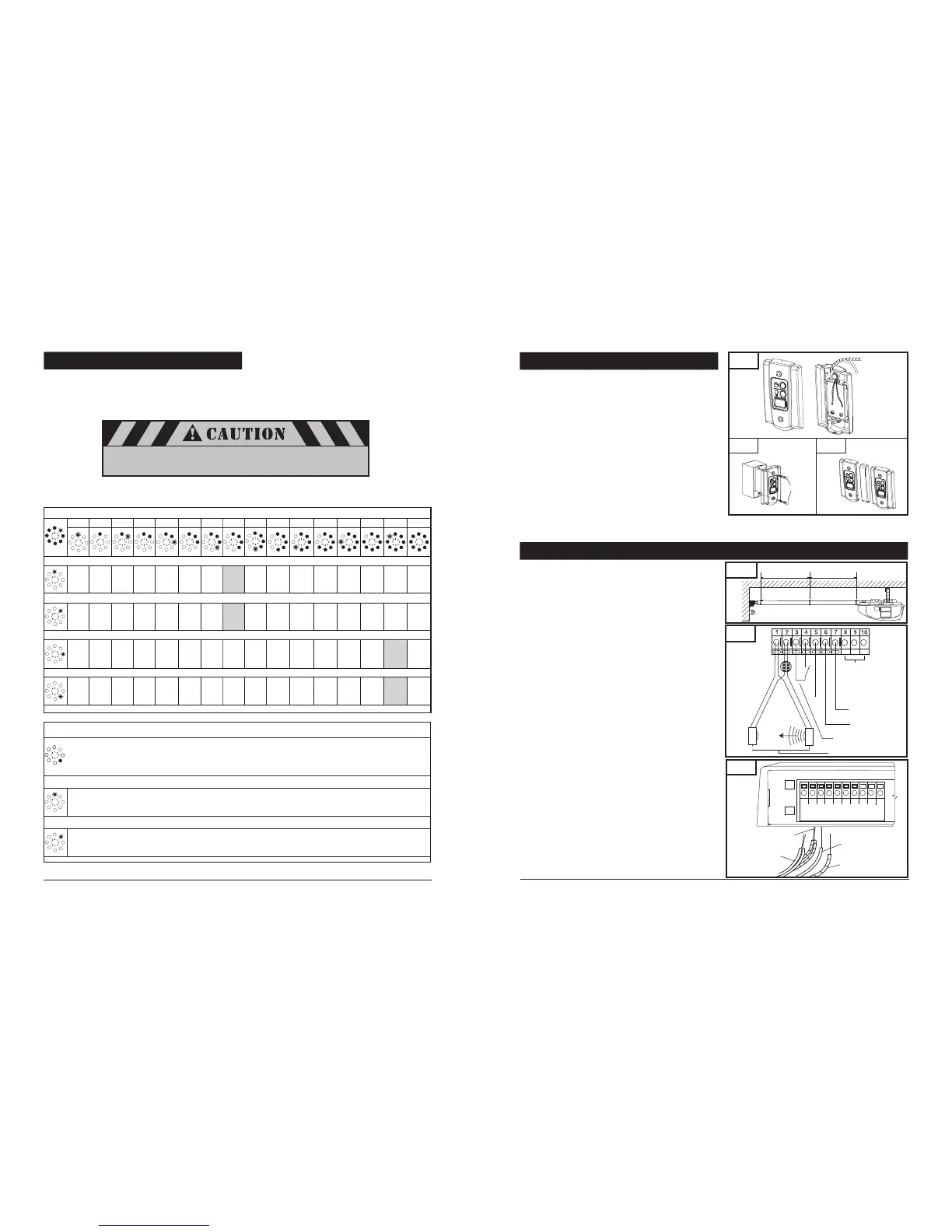
8-11. INSTALL WALL CONTROL PANEL
The control panel must be mounted inside the garage within sight
of the garage door, clear of all moving garage door parts or any
associated parts - and at least 5 feet above the floor to prevent the
use of these controls by children. The device should only be used
when the door is in clear sight of the user and the door area is free
of people or any obstructions.
Attach 2-conductor wire to the screw terminal on back of
control panel. See Fig. 31 (Back). White wire attaches to
terminal #3 screw, white wire with color stripes attaches to
terminal #4 screw.
Position wall control panel onto wall in desired location.
Mark hole location on wall.
Drill 1/16” pilot holes into wall.
Insert and tighten screws to secure control panel to wall.
Make sure wiring is routed out from behind control through
one of the cutouts to avoid pinching the wires.
If mounting to drywall instead of wood, drill 3/16” pilot holes and
use anchors provided. If mounting to electrical box that is prewired
for this purpose, mount directly to box with proper screws provided.
See Fig. 31A.
8-12. CONNECTING THE SAFETY SENSORS AND WALL CONTROL TO OPERATOR
Fig. 32A
24V
Common
(Ground)
Relay
T
R
Wall Control
Photo Eye Sensor System
Not Available
Fig. 32
1/2
1/2
Class 2
Supply 24 Volts
1 2 3 4 5 6 7 8 9 10
Fig. 32B
To Terminal 1
To Terminal 2
To Terminal 4
To Terminal 3
Run wires from the wall control panel along the wall and ceiling
to the operator quick-connect terminals, locate on the rear.
Use the staples to secure wiring to wall, joists and ceiling. Do
not pinch wiring. Drive staples with only enough force to hold
wiring in place. Refer to Fig. 9 on p.7 for an example of typical
wiring routing, and Fig. 32A for terminal assignment.
Insert white single wire from wall control into quick-connect
terminal #3 and single color striped wire into quick-connect
terminal #4.
NOTE:
Individual wall control stations can be combined into one
solid panel.
Detach right side panel from one of the wall controls. (Fig.31B)
Attach wiring to each wall control.
Combine single panels into one block.
Follow the same steps as above to mount additional wall control
panels and wire connections, only connect one wall control
per operator.
Run photo eye system wires along the wall and the top of the
rail assembly to the operator. Use the three wire holders to
secure wires. See Fig. 32.
Insert the stripped end of the white wire combination
firmly into quick-connect terminal #1 by pushing the
wires directly in the terminal hole. If the wires are difficult
to insert, a screwdriver may be used to depress the
terminal "tab" while inserting the wires. To remove wires,
depress the tab again and pull wires out.
Repeat procedure for the stripe wires (white/black stripe),
insert them into quick-connect terminal #2.
NOTE: If wires are difficult to insert, a screwdriver may be
used to depress the quick-connect terminal “tab” while
inserting the wires. To remove wires, depress tab again and
pull wires out.
Fig. 31
Screw caps
4
3
To Terminal #4 Screw
To Terminal #3 Screw
Fig. 31B
Fig. 31A
 Loading...