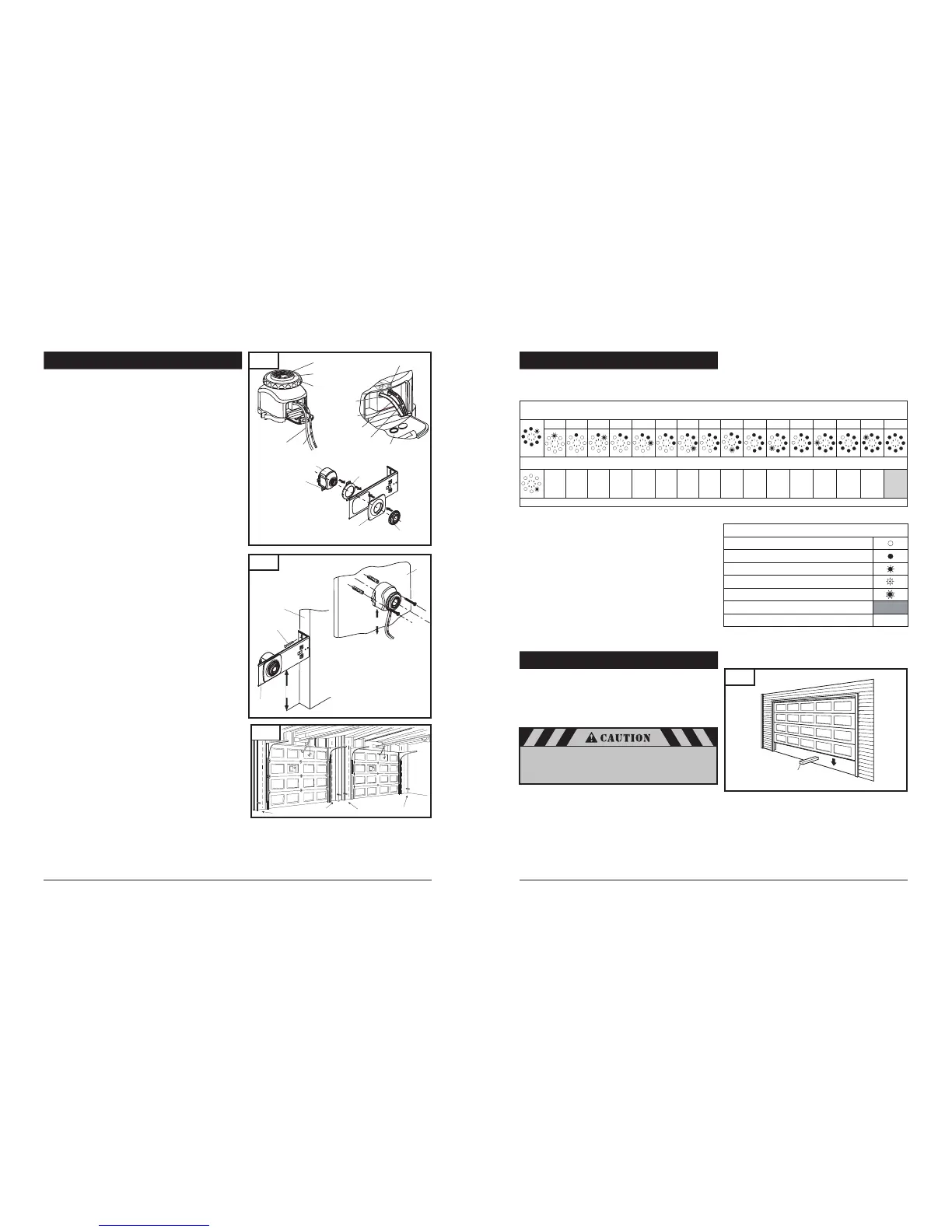
8-10. INSTALL THE PHOTO EYE SENSOR SAFETY SYSTEM
Fig. 28
14
Cover Flap
with Terminal Marking
1
2
TX
Receiver (RX)
or Transmitter (TX)
Mark
Indicator Light
Lens
Fastening
Wheel
Terminal Holes
Wiring to Powerhead
To Terminal 1
To Terminal 2
Tabs
Fig. 29
Wall Stud
Mounting
Bracket
Lag Screws (2)
3" to 4-1/2"
from floor
Sensor Cap
Sensor Cap
Fastener
1
2
2
1
Fastening
Wheel
Photo Eye
Sensor
Wire terminal must
point downward
towards garage floor
Wall
3" to 4-1/2"
from floor
To provide the maximum amount of protection, the photo eye
sensors must be mounted between 3” and 4-1/2” above the floor.
See Fig. 29.
CONNECTING WIRES TO THE PHOTO EYE SENSORS (if
required). Fig. 28
Open the black cover flap.
Insert stripped end of wires into terminal holes by pushing
directly into hole (white wire in terminal #1 and wire with
stripes into terminal #2).
After inserting the wire in the proper terminal, pull on the wire
to ensure proper connection has been made. If the wire pulls
out repeat the above steps.
Place the wires in the slot from the right side of the cover and
close cover.
MOUNTING THE PHOTO EYE SENSORS TO BRACKET
(if required). Fig. 28
Attach the sensor cap and the sensor cap fastener to the
bracket.
Secure the photo eye sensor to the bracket with fastening
wheel.
Repeat process for the other sensor.
MOUNTING THE PHOTO EYE SENSOR BRACKETS TO
WALL:
Locate the mounting position for brackets (bracket can be
mounted in any position as long as photo eye beam will have
a clear path from one side of door to the other side after
mounting).
Use the bracket mounting holes as a template to locate and drill
(2) 3/16" diameter pilot holes on both sides of the garage door
3" to 4-1/2" above the floor.
Secure the bracket assemblies with 1/4" x 1-1/2" lag screws
as shown in Fig. 29.
Align photo eye sensors, so they face each other.
MOUNTING THE PHOTO EYE SENSORS DIRECTLY TO WALL
(optional):
Locate the installation position. See Fig. 29.
Remove sensors from brackets.
Use the photo eye sensor mounting holes as a template to locate
and drill two 1/6” pilot holes into wall (if mounting to drywall
instead of wood, drill two 3/16” pilot holes).
Secure the photo eye sensor assemblies with #6 screws and
anchors (not provided).
Repeat process for the other photo eye sensor.
23
8-17. ADVANCED SETTINGS (cont’d)
8-18. TEST SAFETY REVERSAL
The safety reversal function of your operator is an extremely
important feature of your operator. Testing this function ensures the
correct operation of your operator and door.
The reversal system test should be performed:
Once per month.
Anytime the travel or force limits are reset or changed.
Place a 1-1/2" high rigid object (or a 2x4 board laid flat)
on the floor directly in the path of the door. See Fig. 38.
Start the door in the downward direction and watch what happens.
When door contacts the object, it should stop,
reverse, and automatically return to the fully opened position.
If the door does not reverse, reset the down travel limit
so that the door travels slightly further down in the closed
direction. Then, retest the unit as described above.
If the door still does not reverse, disconnect your operator
and call a service person.
Fig. 38
1-1/2” high rigid object
Legend:
LED off
LED on
LED flashes slowly
LED pulses
LED flashes quickly
Factory default setting
Not possible
–
Level 5 - Special Function
1 2 3 4 5 6 7 8 9 10 11 12 13 14 15 16
Menu 4: Operator Light “ON” Timer (in seconds)
5 10 15 20 25 30 35 40 50 80 100 120 150 180 2552
Level 5: Functions overview
Once the adjustments have been set and the door has
been run up and down twice uninterrupted for the
operator to “learn” the new settings, you must test the
reversal system for proper operation.
Fig. 30
Receiver
Transmitter
Transmitter
Receiver
DUAL DOOR INSTALLATION
In dual door installations, the transmitter (TX) and the receiver
(RX) photo eye sensors (as marked on each of the photo eye
components) should be mounted as indicated in Fig. 30.
TX and RX marks located on the top side of the PCB, near the
terminal area.
 Loading...