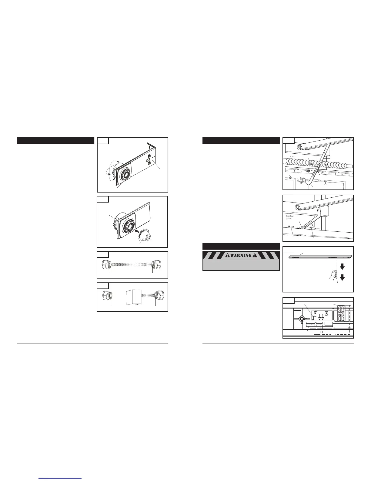
Indicator Window
Fig. 27A
The emergency release cord with red knob, which is already
attached to the trolley, are extremely important parts of the
operator system Fig. 27. Pulling the release cord disengages the
door from the opener. This allows the door to be moved
manually up and down independent of the opener motor.
If the door is in the open position, use extreme care when
using the release.
Use emergency release to disconnect the door if the power is out.
It should also be used if for some unforeseen reason the door
strikes a person or object during its travel and does not automati
-
cally reverse off the obstruction.
To release door - pull firmly down on red knob. (Fig. 27)
Prior to re-engaging door, ensure that all obstructions are
removed and door is operating properly manually. Before
re-engaging trolley with a chain or belt connector, pull down
knob again, then release. The red catch will stop in the “lock”
position and will open indicator window (see Fig. 27A). Now the
door can be reconnected by moving it manually and bringing it
into position when the connector is inside of the trolley.
8-9. CHECK EMERGENCY RELEASE
Fig. 27
A. SECTIONAL DOORS:
Position curved door arm into door bracket channel so that
short end of arm will be attached to door bracket.
See Fig. 25A. Curved door arm should be attached roughly at
the same height as the top rollers of the door.
Align curved door arm and bracket holes, then insert clevis pin
through holes. Attach cotter ring to hold pin in place.
Position straight arm and curved arm to form an angle with
the door (Fig. 25) and at least two sets of holes line up. Select
two overlapping holes as far apart as possible and secure arms
together with hex bolts (5/16-18) and lock nuts.
B. ALL ONE-PIECE DOORS:
Curved door arm should already be attached to trolley in place
of straight door arm. See Fig. 18, p. 10.
Position free end of curved arm into door bracket slot. Align
curved door arm and bracket holes, then insert clevis pin (5/16”
dia.) through holes. Attach cotter ring to pin to hold in place.
See Fig. 26.
C. SECTIONAL AND ONE-PIECE DOORS:
After connecting appropriate door arm, ensure trolley is
disengaged. Check for proper door operation by manually
lifting then lowering to fully opened and closed positions.
Readjust door arm if needed.
PULL DOWN ON RELEASE KNOB TO LOCK TROLLEY, THEN
MOVE DOOR MANUALLY UNTIL TROLLEY LOCKS WITH CHAIN
OR BELT CONNECTOR.
8-8. CONNECT ARM TO DOOR AND TROLLEY (cont’d)
Fig. 40A
Use extreme care when pulling release knob. DO NOT
use knob to pull door open or closed. Except for emer
-
gency situations, use knob only when door is closed.
PHOTO EYE SENSORS ALIGNMENT:
Photo eye sensors maintain an invisible, unbroken beam between
each other. When the photo eye sensors are connected to the
operator and the power is on, the green light on the
transmitter sensor will illuminate. When the sensors are aligned,
the red light on the receiver sensor will illuminate.
NOTE:
Sensor alignment must be done with the door in the closed
position in order to ensure proper visibility of the sensor indicator
LED.
When photo eye system is connected to the operator and
the power is on, the green light on the transmitter sensor will
illuminate. When the sensors are aligned, the red light on the
receiver eye will illuminate.
If necessary loosen the fastening wheel on each photo eye sensor.
Rotate the eye sensor in the sensor cap or slide it inside the
adjustment area of the bracket until eyes are aligned and the
red light on the receiver eye illuminates. See Fig. 39.
Tighten the fastening wheels firmly by hand to secure each
photo eye sensor in position.
If further protection against severe sun light exposure is
required, place the lens sunshield extension on the Receiver
Sensor ONLY. As shown in Fig. 39A.
NOTE:
Identify which side of the garage door opening is exposed to
the most sunlight. Mount the transmitter (TX) sensor on the side
which is exposed to the most sun. Sunlight may affect the Safety
Sensors, and this orientation will help reduce the effect.
SAFETY TEST:
Photo eye sensors installed on opposite sides of your door opening
are intended to detect a person or object in the path of the door
and prevent the door from moving downward. The following steps
will determine if the system is functioning properly:
Open door using the opener’s transmitter or wall control.
Place a box or other object in the path of the door so it breaks
the photo eye beam. See Fig. 40A. Red indicator light on
receiver sensor should go out.
Press and release the wall control button. The door should
not move in the down direction. LED’s # 7 & #8 on the operator
will flash. If this does not happen, disconnect operator and
call for service.
To reset operator, remove the obstruction and operate the
door normally.
If photo eye sensors are not aligned or are damaged, door can
only be closed by pressing and holding wall control button
until door is fully closed.
Fastening Wheel
Bracket
Receiver Sensor
Sunshield Extension
Fig. 39
Object directly in Path between Photo Eye Sensors
Obstruction
Breaking
Infrared Beam
Photo Eye Receiver
(Red Indicator Light Off)
Photo Eye Transmitter
(Green Indicator Light On)
Clear Path between Photo Eye Sensors
Infrared Beam
Photo Eye Receiver
(Red Indicator Light on)
Photo Eye Transmitter
(Green Indicator Light on)
Fig. 39A
Rotation Adjustment
 Loading...