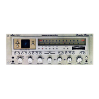
In this circuit (P800), there is no indication of full voltage. The J804 connector provides DC and AC currents to the
oscilloscope, as shown below:
In the above schematic, the conclusion is that the J801 connector provides 7V AC for filaments (in green) and 8V
AC (blue), for the panel lights.
The J802 connector must therefore provide AC voltages to be rectified and generate 576V in DC, as well as 180V
and 41.4V DC supplies. Therefore, the pinout is as follows (all voltages in AC):
The 180V circuit is used to adjust the focus of the oscilloscope, ranging from 50V to 250V. This circuit is derived
from the Marantz 4400.
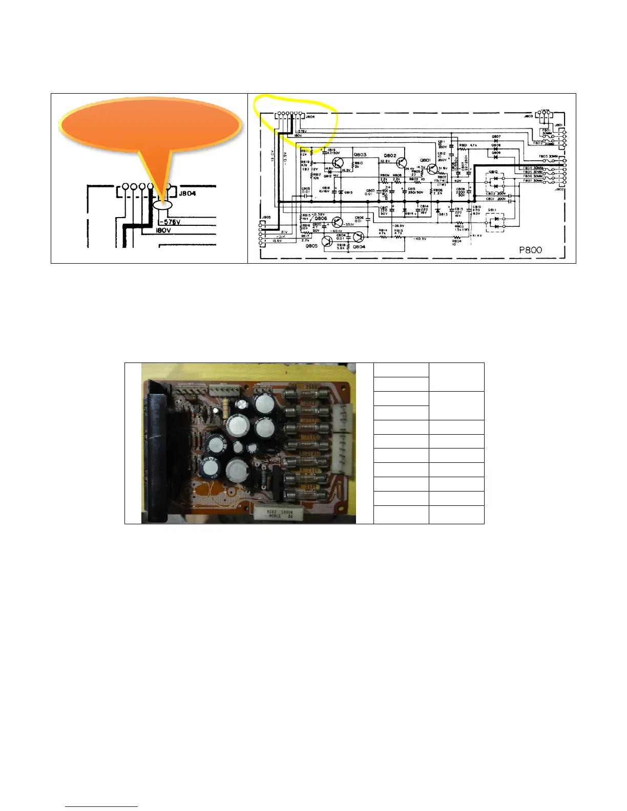
The current of each circuit is indicated on the board. Thus, the analysis is complete this side of the toroidal
transformer. For the amplifier, the currents and the voltages are listed on the next page:
6.3V A.C. for the C.R.T.
filament, plus 576V D.C.