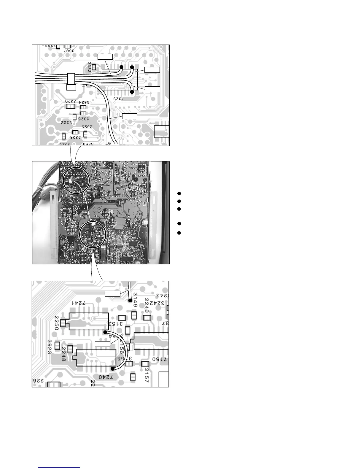
2. DISMOUNTING ADDITIONAL CABLES
1-8
ORG
RED
BRN
EYL
EYL
BLK
BROWM ............ Pin 9 of IC7323
RED ................... Pin 12 of IC7323
ORANGE ........... Pin 15 of IC7323
YELLOW ........... Test Point beside 3149
BLACK............... Pin 7 of IC7240 and Pin 7 of IC7241
REMARK: When replace the CDR loader module
CDRL3610’ to the new one. It is necessary to add
removed cables at same positions as follows;
De-soldering and remove cables from the loader PCB.