95
15. MICROPROCESSOR AND IC DATA
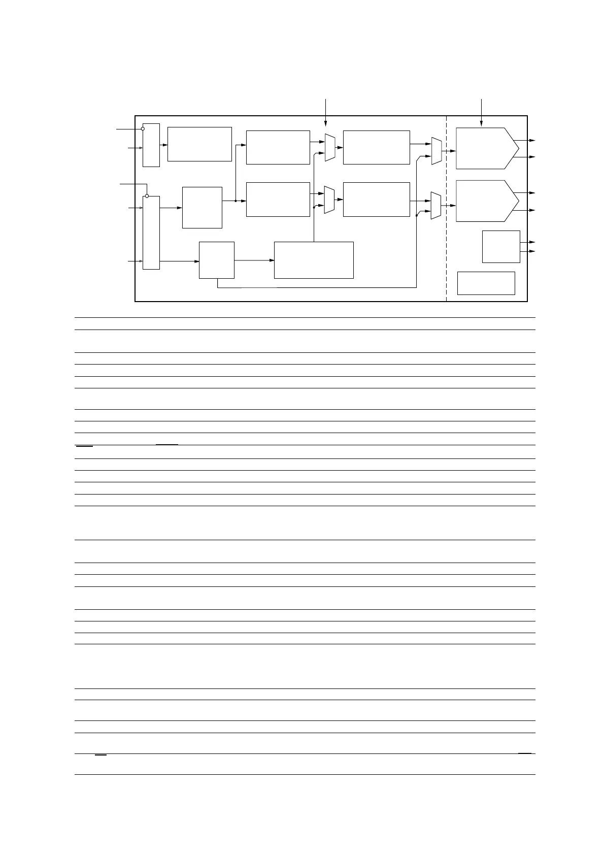
QD01 : CS4398
PCM
Serial
Interface
Multibit
'6Modulator
Interpolation
Filter with
Volume Control
Internal Voltage
Reference
External
Mute
Control
Switched
Capacitor
DAC and
Filter
DSD
Interface
PCM Input
Left and Right
Mute Controls
Right
Differential
Output
Left
Differential
Output
DSD Input
DSD Processor
1.8 V to 5V
1.8 V to 5 V
-Volume control
-50kHz filter
Switched
Capacitor
DAC and
Filter
MUX
Direct DSD
Level Translator
Level
Translator
Hardware or I
2
C/SPI
Control Data
MUX
Multibit
'6Modulator
Interpolation
Filter with
Volume Control
MUX
MUX
3.3 V to 5 V 5 V
Register/Hardware
Configuration
Pin Name # Pin Description
DSD_A
DSD_B
28
1
Direct Stream Digital Input (Input) - Input for Direct Stream Digital serial audio data.
DSD_SCLK
2
DSD Serial Clock (Input) - Serial clock for the Direct Stream Digital audio interface.
SDIN
3
Serial Audio Data Input (Input) - Input for two’s complement serial audio data.
SCLK
4
Serial Clock (Input) - Serial clock for the serial audio interface.
LRCK
5
Left Right Clock (Input) - Determines which channel, Left or Right, is currently active on the serial audio
data line.
MCLK
6
Master Clock (Input) - Clock source for the delta-sigma modulator and digital filters.
VD
7 Digital Power (Input) - Positive power for the digital section.
DGND
8
Digital Ground (Input) - Ground reference for the digital section.
RST
13
Reset (Input) - The device enters system reset when enabled.
VLC
14
Control Port Power (Input) - Positive power for Control Port I/O.
FILT+
15
Positive Voltage Reference (Output) - Positive reference voltage for the internal sampling circuits.
REF_GND
16
Reference Ground (Input) - Ground reference for the internal sampling circuits.
VREF
17 Voltage Reference (Input) - Positive voltage reference for the internal sampling circuits.
BMUTEC
AMUTEC
18
25
Mute Control (Output) - The Mute Control pin is active during power-up initialization, muting, power-
down or if the master clock to left/right clock frequency ratio is incorrect. During reset these outputs are
set to a high impedance.
AOUTB+
AOUTB-
20
19
Differential Right Channel Analog Output (Output) - The full scale differential analog output level is
specified in the Analog Characteristics specification table.
AGND
21
Analog Ground (Input) - Ground reference for the analog section.
VA
22 Analog Power (Input) - Positive power for the analog section.
AOUTA+
AOUTA-
23
24
Differential Left Channel Analog Output (Output) - The full scale differential analog output level is
specified in the Analog Characteristics specification table.
VQ
26 Quiescent Voltage (Output) - Filter connection for internal quiescent voltage.
VLS
27
Serial Audio Interface Power (Input) - Positive power for serial audio interface I/O.
Stand Alone Mode Definitions
M3
M2
M1
M0
9
10
11
12
Mode Selection (Input) - Determines the operational mode of the device.
Control Port Mode Definitions
AD1/CDIN
9
Address Bit 1 (I²C) / Control Data Input (SPI) (Input) - AD1 is a chip address pin in I²C mode; CDIN is
the input data line for the Control Port interface in SPI mode.
SCL/CCLK
10
Serial Control Port Clock (Input) - Serial clock for the serial Control Port.
SDA/CDOUT
11
Serial Control Data (I²C) / Control Data Output (SPI) (Input/Output) - SDA is a data I/O line in I²C
mode. CDOUT is the output data line for the Control Port interface in SPI mode.
AD0/CS
12
Address Bit 0 (I²C) / Control Port Chip Select (SPI) (Input) - AD0 is a chip address pin in I²C mode; CS
is the chip select signal for SPI format.
 Loading...